KS4022/KS4023 EASY Plug Ultimate Starter Kit for BBC Micro:bit STEM EDU
Resource:
Download code ,CoolTerm software ,Driver and more details, please refer to the following link: https://fs.keyestudio.com/KS4022-4023
1. Description
Micro:bit is significantly applied to STEM education for teenagers, as a small microcontroller, which features small in size, easy to carry, and powerful function. At present, innovative technology products, like robots, wearable devices and interactive electronic games can be produced by programming and code.
MakeCode is a framework for creating interactive and engaging programming experiences for those new to the world of programming. The platform provides the foundation for a tailored coding experience to create and run user programs on actual hardware or in a simulated target.
To make you deeply know the micro:bit, we also provide test code and projects.
This ultimate starter kit incorporates different sensors and modules such as passive buzzer, 1602 LCD module, RGB, flame sensor and so on. The detailed projects, from simple to difficult will spur your inspiration and bring in the magical programming world.
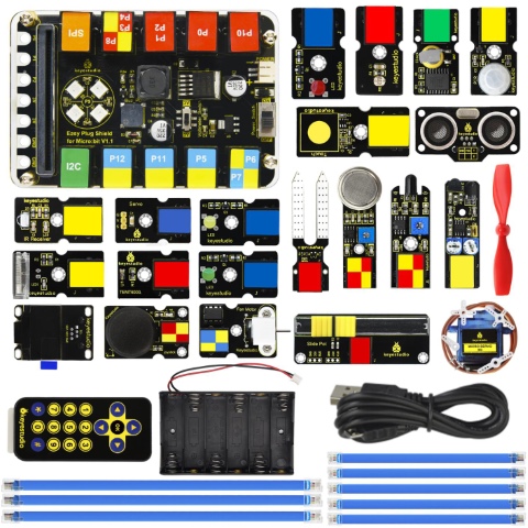
2. Kit List
# |
Component |
QTY |
Picture |
|---|---|---|---|
0 |
Micro:bit main board is not included in KS4022 Kit |
1 |
|
1 |
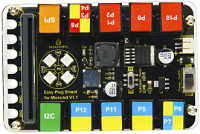
EASY Plug Shield for micro bit V1.1 |
1 |
|
2 |
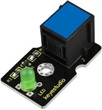
EASY Plug Green LED Module |
1 |
|
3 |
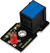
EASY Plug Yellow LED Module |
1 |
|
4 |
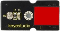
EASY Plug Red LED Module |
1 |
|
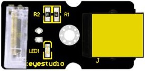
5 |
EASY Plug Photoresistor |
1 |
|
6 |
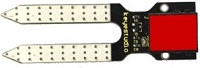
EASY Plug Soil Humidity Sensor |
1 |
|
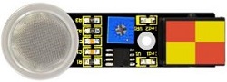
7 |
EASY Plug Analog Gas Sensor |
1 |
|
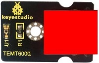
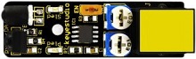
8 |
EASY Plug TEMT6000 Ambient Light Sensor |
1 |
|
9 |
EASY Plug Slide Potentiometer Module |
1 |
|
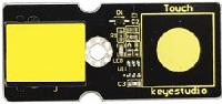
10 |
EASY Plug Capacitive Touch Module |
1 |
|
11 |
EASY Plug Knock Sensor |
1 |
|
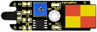
12 |
EASY Plug Flame Sensor |
1 |
|
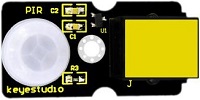
13 |
EASY Plug PIR Motion Sensor |
1 |
|
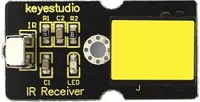
14 |
EASY Plug IR Receiver |
1 |
|
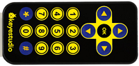
15 |
Keyestudio IR Remote Control |
1 |
|
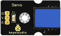
16 |
EASY Plug Servo Module |
1 |
|
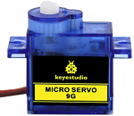
17 |
Keyestudio 9G Servo 90° |
1 |
|
18 |
EASY Plug IR Obstacle Avoidance Sensor |
1 |
|
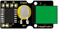
19 |
EASY Plug DS3231 Clock Module |
1 |
|
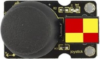
20 |
EASY Plug Joystick Module |
1 |
|
21 |
EASY Plug SR01 Ultrasonic Sensor |
1 |
|
22 |
EASY Plug OLED Module |
1 |
|
23 |
EASY Plug L9110 Fan Module |
1 |
|
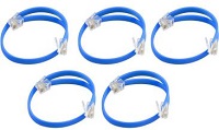
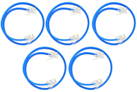
24 |
200mm Blue RJ11 Cable |
5 |
|
25 |
300mm Blue RJ11 Cable |
3 |
|
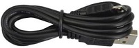
26 |
Micro USB Cable |
1 |
|
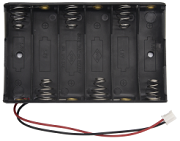
27 |
6-Slot AA Battery Holder |
1 |
|
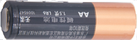
28 |
1.5V AA Battery(Not Included) |
6 |
|
3. Introduction
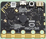
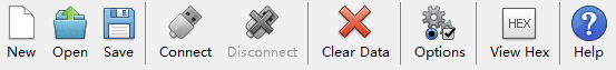
( 1 ) What is Micro:bit?
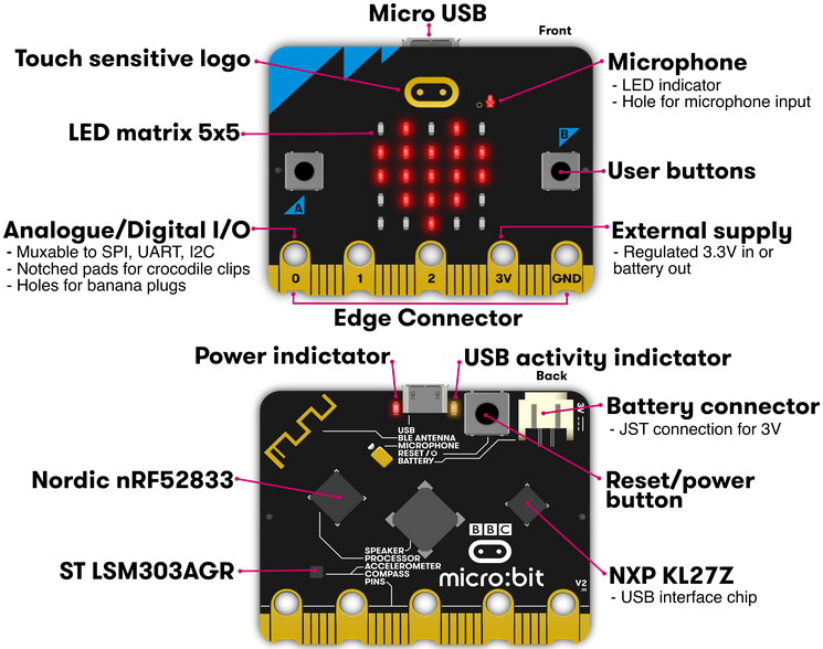
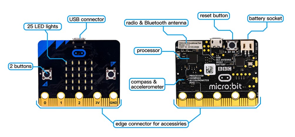
Designed by BBC, Micro:bit main board aims to help children aged above 10 years old to have a better learning of programming.
It is equipped with loads of components,including a 5*5 LED dot matrix, 2 programmable buttons, a compass, a Micro USB interface and a Bluetooth module and others. Though it is just the size of a credit card, it boasts multiple functions. To name just a few, it can be applied in programming video games, making interactions between light and sound, controlling a robot, conducting scientific experiments, developing wearable devices and make some cool inventions like robots and musical instruments, basically everything imaginable.
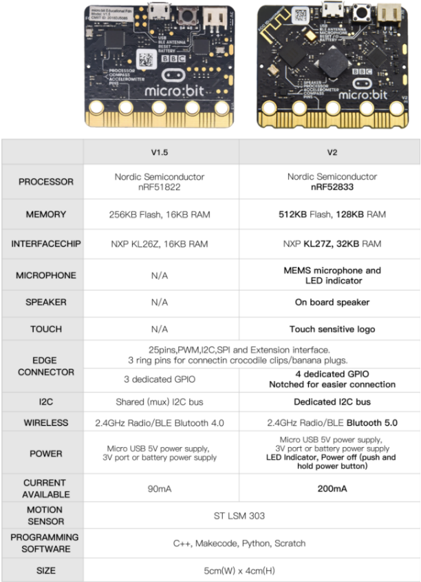
The latest version, that’s version 2.0, of Micro:bit main board has a touch-sensitive logo and a MEMS microphone. And there is a buzzer built in the other side of the board which makes playing all kinds of sound possible without any external equipment. The golden fingers and gears added provide a better fixing of crocodile clips. Moreover, this board has a sleeping mode to lower the power consumption of battery and it can be entered if users long press the Reset & Power button on the back of it. More importantly, the CPU capacity of this version is much better than that of the V1.5 and the V2 has more RMA.
In final analysis, the Micro:bit main board V2 can allow customers to explore more functions so as to make more innovative products.
( 2 ) Comparison between V2.0 & V1.5
Micro:bit main Board V2.0
Micro:bit main Board V1.5
More details:
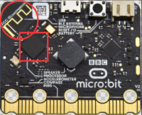
For the Micro: Bit main board V2, pressing the Reset & Power button , it will reset the Micro: Bit and rerun the program. If you hold it tight, the red LED will slowly get darker. When the power indicator becomes darker, releasing the button and your Micro: Bit board will enter sleep mode for power saving .This will make your battery more durable. And you could press this button again to ‘wake up’ your Micro:bit.
For more information,please resort to following links:
https://tech.microbit.org/hardware/ https://microbit.org/new-microbit/ https://www.microbit.org/get-started/user-guide/overview/ https://microbit.org/get-started/user-guide/features-in-depth/
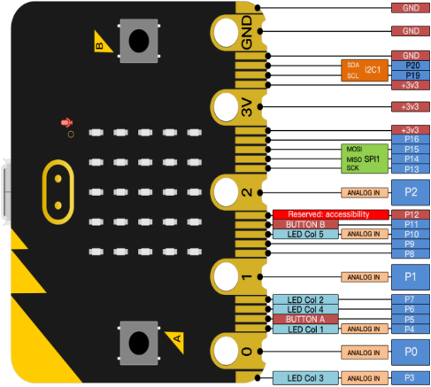
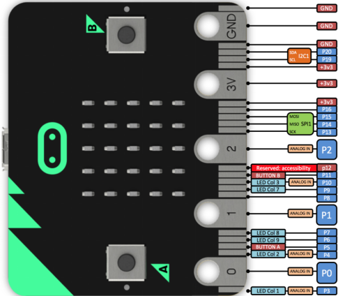
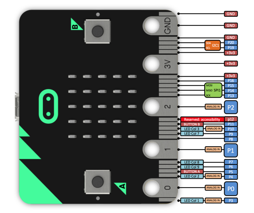
( 3 ) Pinout
Micro:bit main board V2.0 VS V1.5
Browse the official website for more details:
https://tech.microbit.org/hardware/edgeconnector/
https://microbit.org/guide/hardware/pins/
( 4 ) Notes for the application of Micro:bit main board V2.0
a. It is recommended to cover it with a silicone protector to prevent short circuit for it has a lot of sophisticated electronic components.
b. Its IO port is very weak in driving since it can merely handle current less than 300mA. Therefore, do not connect it with devices operating in large current,such as servo MG995 and DC motor or it will get burnt. Furthermore, you must figure out the current requirements of the devices before you use them and it is generally recommended to use the board together with a Micro:bit shield.
c. It is recommended to power the main board via the USB interface or via the battery of 3V. The IO port of this board is 3V, so it does not support sensors of 5V. If you need to connect sensors of 5 V, a Micro: Bit expansion board is required.
d.When using pins(P3, P4, P6, P7, P10)shared with the LED dot matrix, blocking them from the matrix or the LEDs may display randomly and the data about sensors maybe wrong.
e.The battery port of 3V cannot be connected with battery more than 3.3V or the main board will be damaged.
f. Forbid to use it on metal products to avoid short circuit.
To put it simple, Micro:bit V2 main board is like a micro computer which has made programming at our fingertips and enhanced digital innovation. And about programming environment, BBC provides a website: https://microbit.org/code/, which has a graphical MakeCode program easy for use.
4. Install Micro:bit Driver
If you have downloaded micro:bit driver, then no need to download it again.
If it is you first time to use micro:bit main board, then you will have to download the driver.
First of all, connect the micro:bit to your computer using a USB cable.
And enter the link https://fs.keyestudio.com/KS4022-4023 to download the driver file of micro:bit,  .
.
5. Getting Started with Micro:bit
The following instructions are applied for Windows system but can also serve as a reference if you are using a different system.
5.1 Write code and program
This chapter describes how to write program with the App Micro: Bit and load the program to the Micro: Bit main board V2. You are recommended to browse the official website of Micro:bit for more details, and the link is attached below:
https://microbit.org/guide/quick/
Step 1: connect the Micro: Bit main board V2 with your computer
Firstly, link the Micro: Bit main board V2 with your computer via the USB cable. Macs, PCs, Chromebooks and Linux (including Raspberry Pi)systems are all compatible with the Micro: Bit main board V2.
Note that if you are about to pair the board with your phone or tablet, please refer to this link:
https://microbit.org/get-started/user-guide/mobile/
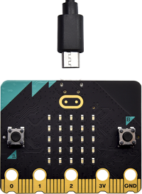
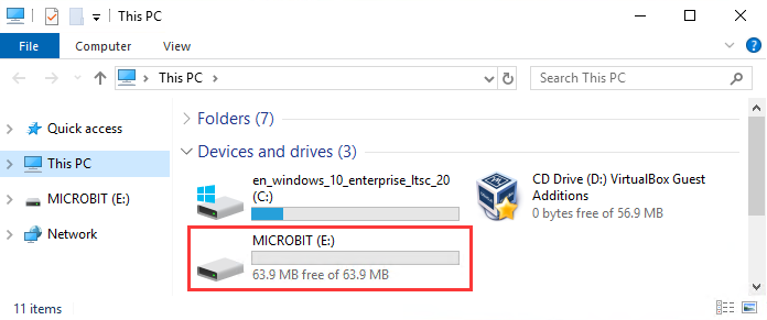
Secondly, if the red LED on the back of the board is on, that means the board is powered. Then Micro: Bit main board V2 will appear on your computer as a driver named ‘MICROBIT’. Please note that it is not an ordinary USB disk as shown below.
Step 2: writing programs
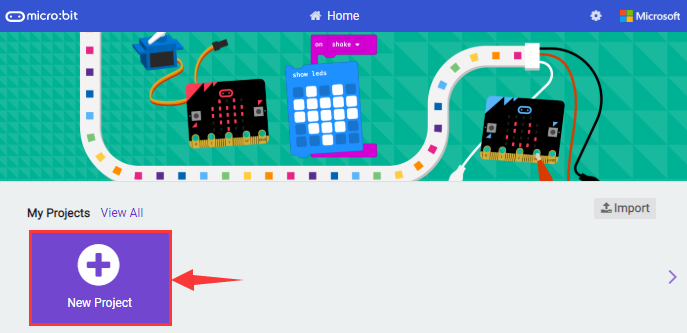
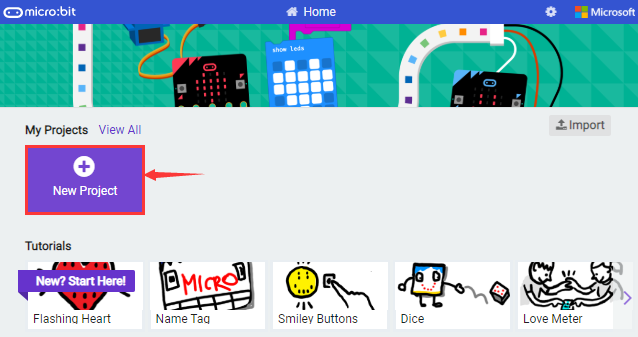
View the link https://makecode.microbit.org/ in your browser;
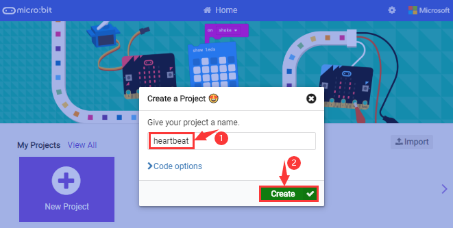
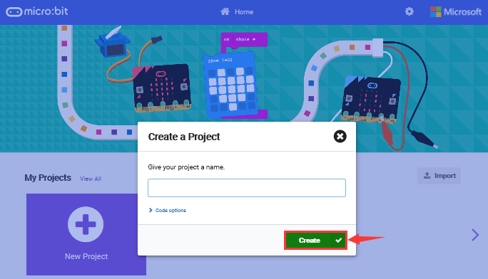
Click  ; The dialog box
  appears, fill it with ‘heartbeat’ and click
  to edit.
(If you are running Windows 10 system, it is also viable to edit on the APP MakeCode for micro:bit , which is exactly like editing in the website. And the link to the APP is https://www.microsoft.com/zh-cn/p/makecode-for-micro-bit/9pjc7sv48lcx?ocid=badgep&rtc=1&activetab=pivot:overviewtab)
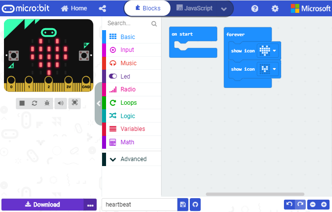
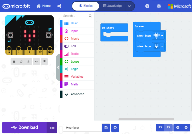
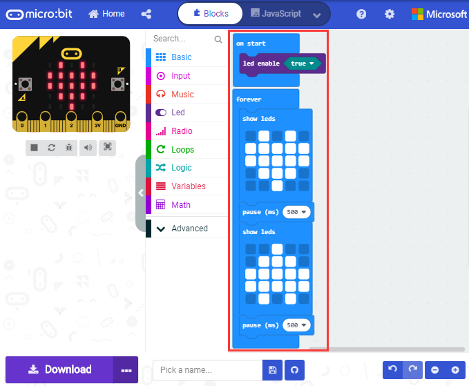
Write a set of micro:bit code. You can drag some modules in the Blocks to the editing area and then run your program in Simulator of MakeCode editor as shown in the picture below which demonstrates how to edit ‘heartbeat’ program .
As for loading test code , please turn to Chapter 5.5.
And introduction of Makecode is on the next chapter 5.2.
Step 3: download test code
If your computer is Windows 10 and you have downloaded the APP MakeCode for micro:bit to write program, what you will have to do to download the program to your Micro: Bit main board V2 is merely clicking the ‘Download’ button, then all is done.
If you are writing programs through the website, following these steps:
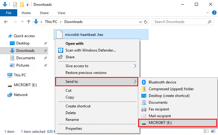
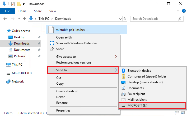
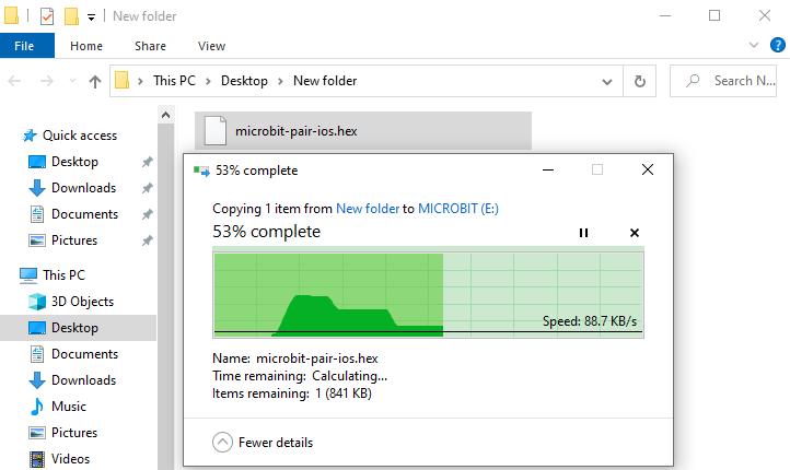
Click the ‘Download’ in the editor to download a “hex” file, which is a compact program format that the Micro: Bit main board can read. Once the hexadecimal file is downloaded, copy it to your board V2 just like the process that you copy the file to the USB driver. If you are running Windows system, you can also right-click and select ‘Send to → Microbit (E) ‘to copy the hex file to the Micro: Bit main board V2.
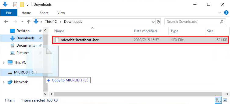
You can also directly drag the “hex” file onto the MICROBIT (E) disk.

During the process of copying the downloaded hex file to the Micro: Bit main board V2, the yellow signal light on the back side of the board flashes. When the copy is completed, the yellow signal light will stop flashing and remain on.
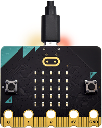
Step 4: run the program
After the program is uploaded to the Micro: Bit main board V2, you could still power it via the USB cable or change to via an external power. The 5 x 5 LED dot matrix on the board displays the heartbeat pattern.
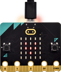
micro USB cable
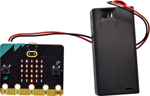
external power(3V)
Step 5: other programming languages
This chapter has described how to use the Micro: Bit main board V2.
But except for the Makecode graphical programming introduced you can also write Micro: Bit programs in other languages. Go to the link: https://microbit.org/code/ to know about other programming languages, or view the link: https://microbit.org/projects/, to find something you want to have a go.
5.2 Makecode
Browse https://makecode.microbit.org/ and enter Makecode online editor or open the APP MakeCode for micro:bit of Windows 10.
Click , and input “heartbeat”, then enter Makecode editor, as shown below:
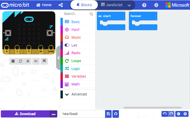
There are block  and
and  in the code editing area.
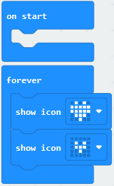
When the power is plugged or reset, “on start” means that blocks in the code are only executed once, “forever” implies that code will run cyclically.
5.3. Quick Download
As mentioned before, if your computer is Windows 10 and you have downloaded the APP MakeCode for micro:bit to write programs, the program written can be quickly downloaded to the Micro: Bit main board V2 by selecting  .
.
While it is a little more trickier if you are using a browser to enter makecode. However, if you use Google Chrome, suitable for Linux, macOS and Windows 10, the process can be quicker too.
We use the webUSB function of Chrome to allow the internet page to access the hardware device connected USB.
You could refer to the following steps to connect and pair devices.
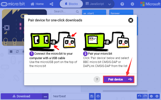
Pairing device
Connect micro:bit to your computer by USB cable. Click  beside “Download” and click
  .
.
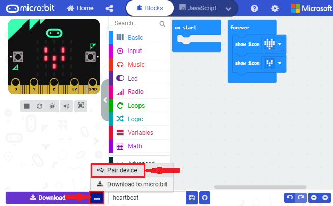
Then click another  as shown below.
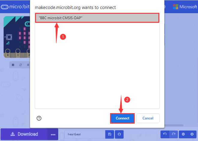
Tap “BBC micro:bit CMSIS-DPA” and click  . If
. If  does not show up for selection, please refer to https://makecode.microbit.org/device/usb/webusb/troubleshoot
We also provide  in the resource link.
What’s more, if you don’t know how to update the firmware of micro:bit, refer to the link: https://microbit.org/guide/firmware/ or browse folder we provide.
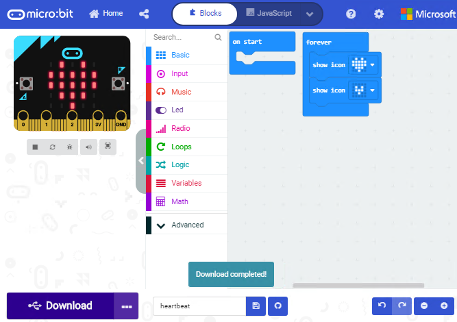
Then click  . The program is directly downloaded to Micro: Bit main board V2 and the sentence “Download completed!” appears.
5.4 Resources and test code
Tools ,test code and other resources can be downloaded via the link https://fs.keyestudio.com/KS4022-4023
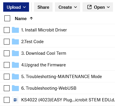
Download and unzip the file, you will see a file clip named KS4022 (4023)EASY Plug Ultimate Starter Kit for BBC Micro:bit STEM EDU, and it contains following files:
5.5 Import test code
We provide hexadecimal code files (project files) for each project. The file contains all the contents of the project and can be imported directly, or you can manually drag the code blocks to complete the program for each project.
For simple projects, dragging a block of code to complete the program is recommended. For complex projects, it is recommended to conduct the program by importing the hexadecimal code file we provide.
Let’s take the “Heatbeat” project as an example to show how to load the code.
Open the Web version of Makecode or the Windows 10 App version of Makecode.
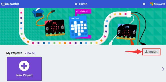
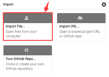
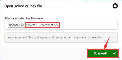
Click “Import File”;
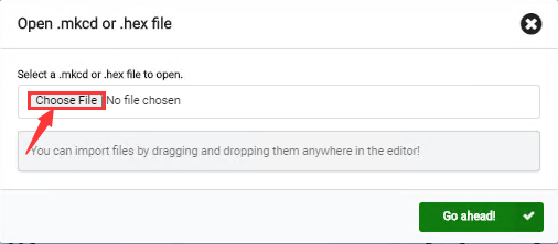
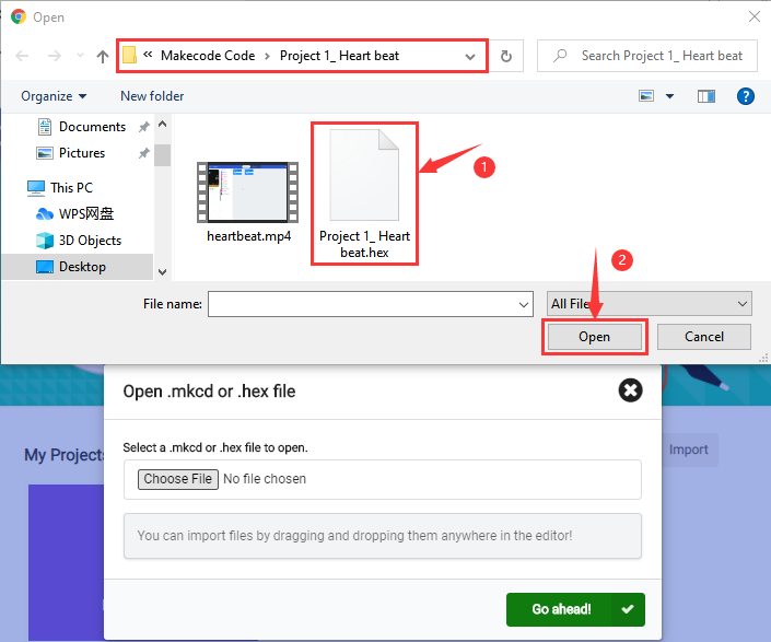
Select “ ../Makecode Code/Project 1_ Heart beat/Project 1_ Heart beat.hex” ;
Then click  .
.
In addition to importing the test code file provided into the Makecode compiler above, you can also drag the the test code file provided into the code editing area of the Makecode compiler, as shown in the figure below:
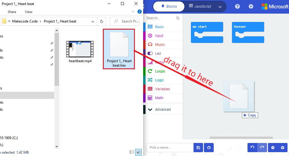
After a few seconds, it is done.
Note: if your computer system is Windows 7 or 8 instead of Windows 10, the pairing cannot be done via Google Chrome. Therefore, digital signal or analog signal of sensors and modules cannot be shown on the serial port simulator. However, you need to read the corresponding digital signal or analog signal.
So what can we do? You can use the CoolTerm software to read the serial port data of the micro:bit. Next chapter is about how to install CoolTerm.
5.6 CoolTerm Installation
CoolTerm program is used to read the data on serial port.
Download CoolTerm program:
Link of Download: https://freeware.the-meiers.org/
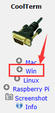
1.After the download, we need to install CoolTerm program file, below is Window system taken as an example.
2.Choose “win ” to download the zip file of CoolTerm
3.Unzip file and open it. (also suitable for Mac and Linux system)
4.Double-click  .
.
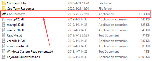
The functions of each button on the Toolbar are listed below:
ICON |
Function |
|---|---|
|
Opens up a new Terminal |
|
Opens a saved Connection |
|
Saves the current Connection to disk |
|
Opens the Serial Connection |
|
Closes the Serial Connection |
|
Clears the Received Data |
|
Opens the Connection Options Dialog |
|
Displays the Terminal Data in Hexadecimal Format |
|
Displays the Help Window |


6. Projects
(Note: project 1 to 12 will be conducted with the built-in sensors and LED dot matrix of the Micro:bit main board V2)
Project 1: Heartbeat
Project Description:
This project is easy to conduct with a micro:bit V2 main board, a Micro USB cable and a computer. The micro:bit LED dot matrix will display a relatively big heart-shaped pattern and then a smaller one. This alternative change of this pattern is like heart beating. This experiment serves as a starter for your entry to the programming world.
Components Needed:
Micro:bit main board V2 *1
Micro USB cable*1
Test Code:
Attach the Micro:bit main board V2 to your computer via the Micro USB cable and begin editing.
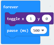
Firstly, click  and find and drag the block
 to “forever”;

Secondly, click again and find and drag the block to module “forever” and click the little triangle to select  ;
;
Thirdly, click and find and drag the block  to the code block and click the littler triangle to select 500;
Complete Program:
|
①In“on start”the program only runs once; |
|---|---|
 ”;
”; ”
”Note: the “on start” means that blocks in the code are only executed once, “forever” implies that code will run cyclically.
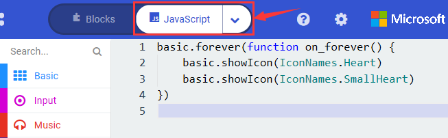
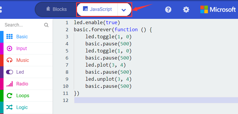
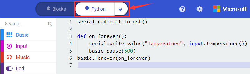
Click  , you will find the corresponding programming languages.
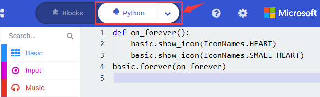
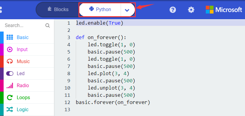
Click  to choose
  , you will find the corresponding Python programming languages.
Test Results:
Uploading test code to micro:bit main board V2 and keeping the connection with the computer to power the main board, the LED dot matrix shows pattern “ ”and then “
 ”alternatively.
(Please refer to chapter 5.3 to know how to download test code quickly.)
If the downloading is not smooth, please remove the micro USB from the main board and then reconnect them and reopen Makecode to try again.
Project 2: Light A Single LED
Project Description:
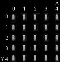
The LED dot matrix consists of 25 LEDs arranged in a 5 by 5 square. In order to locate these LEDs quickly, as the figure shown below, we can regarded this matrix as a coordinate system and create two aces by marking those in rows from 0 to 4 from top to bottom, and the ones in columns from 0 to 4 from the left to the right. Therefore, the LED sat in the second of the first line is (1,0)and the LED positioned in the fifth of the fourth column is (3,4)and others likewise.
Components Needed:
Micro:bit main board V2 *1
Micro USB cable*1
Test Code:
Attach the Micro:bit main board V2 to your computer via the Micro USB cable and begin editing.
Firstly, click  and then the
  to find and drag the block
 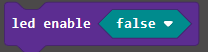 to block “on start”; and click
  to select
  ;
;
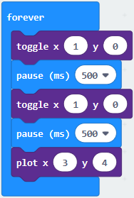
Secondly, click  and to find and drag the block
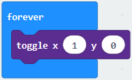
 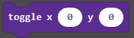 to block “forever” and alter “x0” to”x1”;
Thirdly, click to find and drag the block 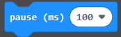 to “forever” block and set pause to 500;
Fourthly, copy the block 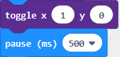 and place it into “forever” block;
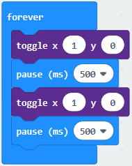
Fifthly, click to find and drag the block 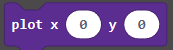 to “forever” block and change the “x 0 y 0” to “x 3 y 4”;
Sixthly, copy the block “pause(ms)500” and place it into “forever” block;
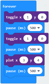
Lastly, click to find and drag the block  to “forever” and change “x 0 y 0” to “x 3 y 4”; and copy and place the block “pause(ms)500” to block “forever”;
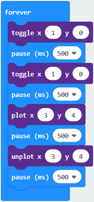
Complete Program:
|
①In“on start”the program only runs once; |
|---|---|
Click , you will find the corresponding programming languages.
Click to choose , you will find the corresponding Python programming languages.
Test Results
Uploading test code to micro:bit main board V2 and powering the main board via the USB cable, the LED in (1,0) lights up for 0.5s and the one in (3,4) shines for 0.5s and repeat this sequence.
Project 3: LED Dot Matrix
Project Description:
Dot matrices are very commonplace in daily life. They have found wide applications in LED advertisement screens, elevator floor display, bus stop announcement and so on.
The LED dot matrix of Micro: Bit main board V2 contains 25 LEDs in a grid. Previously, we have succeeded in controlling a certain LED to light by integrating its position value into the test code. Supported by the same theory, we can turn on many LEDs at the same time to showcase patterns, digits and characters.
What’s more, we can also click”show icon“ to choose the pattern we like to display. Last but not the least, we can our design patterns by ourselves.
Components Needed:
Micro:bit main board V2 *1
Micro USB cable*1
Test Code 1:
Link computer with micro:bit board by micro USB cable, and program in MakeCode editor.
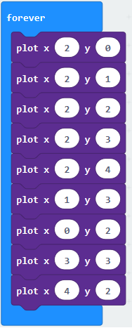
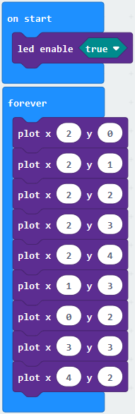
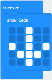
Enter → → ; Click to select :
Combine it with “on start” block
*****************************************************************
Click to move into“forever”, then replicate for 8 times, respectively set to“x 2”y 0”, “x 2”y 1”, “x 2”y 2”, “x 2”y 3”, “x2”y 4”, “x 1”y 3”, “x 0”y 2”, “x 3”y 3”, “x 4”y 2”.
Complete Program:
|
“on start”: command block only runs once to start program. |
|---|---|
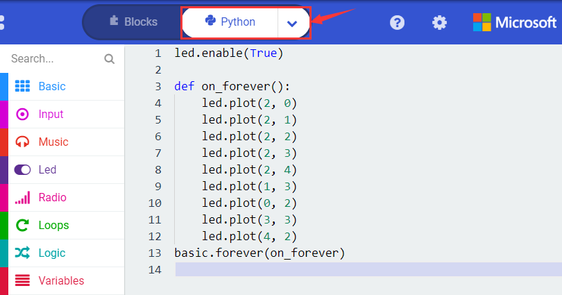
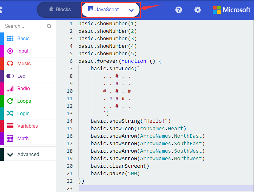
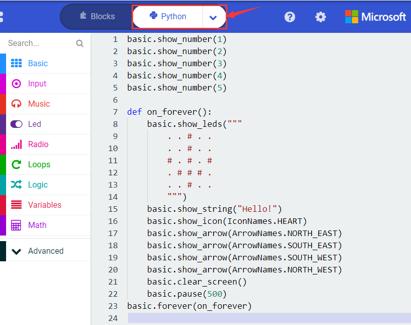
Select and  to switch into JavaScript and Python code:
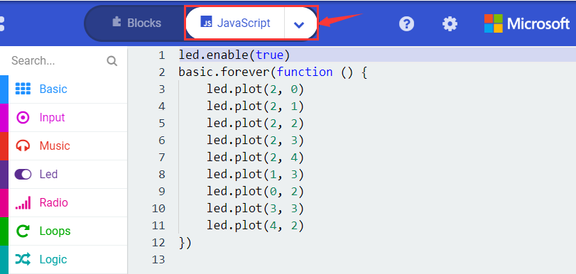
Test Results 1:
Upload code 1 and power on , we will see the  icon.
icon.
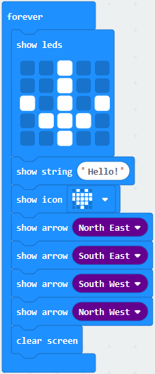
Test Code 2:
Link computer with micro:bit board by micro USB cable, and program in MakeCode editor.
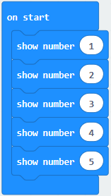
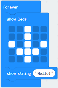
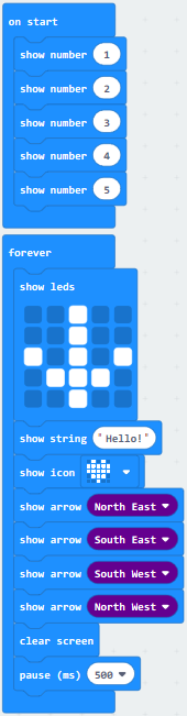
Enter → 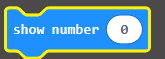 → Duplicate it for 4 times, separately set number to 1, 2, 3, 4, 5.
*****************************************************************
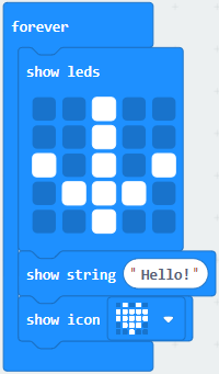
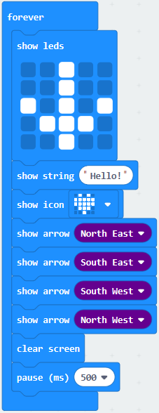
Click →  → put it into “forever” block, tick blue boxes to light LED and generate “↓” pattern.
*****************************************************************
Move out the block  from block, and leave it beneath the block.
Choose 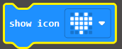 from , and leave it beneath
*****************************************************************
Enter → 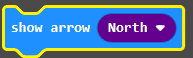 → replicate for 3 times, respectively set to “North East”, “South East”, “South West” “North West”.
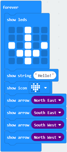
Click to get  then remain it below
*****************************************************************
Drag  from and set to 500ms, then leave it below .
Complete Program:
|
“on start”: |
|---|---|
Select and to switch into JavaScript and Python code:
Test Results 2:
Upload code 2 and plug micro:bit to power. Micro: bit starts showing number 1, 2, 3, 4, and 5, then cyclically display,“Hello!”,  ,
,  ,
,  ,
,  and
and  patterns.
Project 4: Programmable Buttons
Project Description:
Buttons can be used to control circuits. In an integrated circuit with a button, the circuit is connected when pressing the button and it is open the other way around.
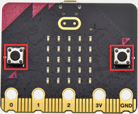
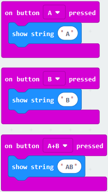
Micro: Bit main board V2 boasts three buttons, two are programmable buttons(marked with A and B), and the one on the other side is a reset button. By pressing the two programmable buttons can input three different signals. We can press button A or B alone or press them together and the LED dot matrix shows A,B and AB respectively. Let’s get started.
Components Needed:
Micro:bit main board V2 *1
Micro USB cable*1
Test Code 1:
Link computer with micro:bit board by micro USB cable, and program in MakeCode editor,
Delete “on start” and “forever” firstly,then click  →
→ 
*****************************************************************
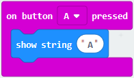
A. Click → 
B. Then place it into “on button A pressed”, change “Hello!” into “A”.
Copy code stringonce, tap the drop-down button “A” to select “B” and modify character “A” into “B”.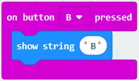
*****************************************************************
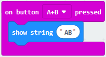
Copy
once,and set to“on
button A+B pressed”and“show string “AB”
*****************************************************************
Complete Code:
|
Press button A on Micro: bit main board |
|---|---|
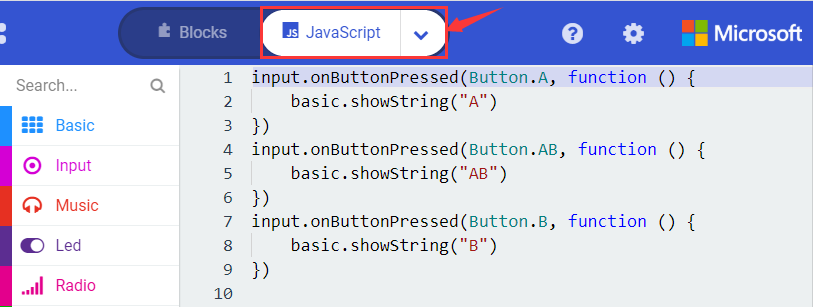
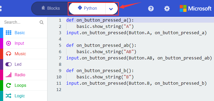
Select “JavaScript” and “Python” to switch into JavaScript and Python language code:
Test Results 1:
Uploading test code 1 to micro:bit main board V2 and powering the main board via the USB cable, the 5*5 LED dot matrix shows A if button A is pressed, B if button B pressed, and AB if button A and B pressed together.
Test Code 2:
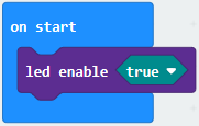
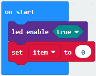
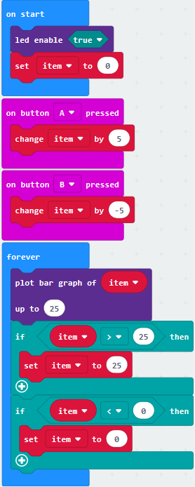
A. Click “Led” → “more” → “led enable false”,
B. Put it into the block “on start”, click drop-down triangle button to select “true” .
.
*****************************************************************
A. Tap “Variables” → “Make a Variable…” → “New variable name:”
B. Enter “item” in the dialog box and click “OK”,then variable “item” is produced. And move“set item to 0”into“on start”block
*****************************************************************
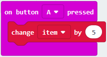
A. Click “Input” → “on button A pressed”.
B. Go to “Variables”→“ change item by 1 ”
C. Place it into“on button A pressed”and 1 is modified into 5.
*****************************************************************
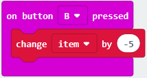
Duplicatecode string once,click the drop-down button to select“B”,then set“change item by
-5”.
*****************************************************************
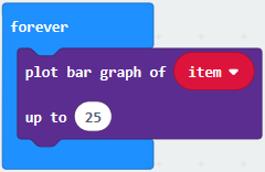
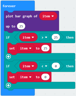
A. Enter“Led”→“plot bar graph of 0 up to 0”
B. Keep it into“forever”block
C. Go to“Variables”to move“item”into 0 box,change 0 into 25.
*****************************************************************
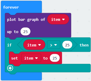
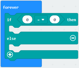
(6)A. Go to“Logic”to move out “if…true…then…”and “=”blocks,
B. Keep“=”into“true”box and set to “>”
C. Select“item”in the“Variables”and lay it down at left box of “>”,change 0 into 25;
D. Enter“Variables”to drag“set item to 0”block into“if…true..then…”, alter 0 into 25.
*****************************************************************
(7) A. Replicate code string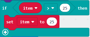 once
once
B.“>” is modified into “<” and 25 is changed into 0,
C. Leave it beneath code string.
Complete Program:
|
“on start”: |
|---|---|
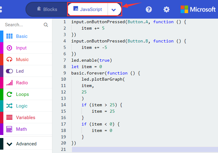
Select“JavaScript” and“Python”to switch into JavaScript and Python language code:
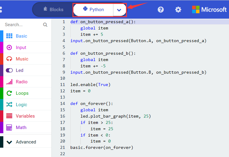
Test Results 2:
Uploading test code 2 to micro:bit main board V2 and powering the main board via the USB cable, when pressing the button A the LEDs turning red increase while when pressing the button B the LEDs turning red reduce.
Project 5: Temperature Detection
Project Description:
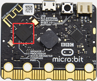
Actually ,the Micro:bit main board V2 is not equipped with a temperature sensor, but uses the temperature sensor built into NFR52833 chip for temperature detection. Therefore, the detected temperature is more closer to the temperature of the chip, and there maybe deviation from the ambient temperature.
Components Needed:
Micro:bit main board V2 *1
Micro USB cable*
Test Code 1:
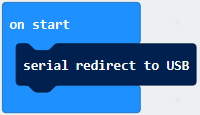
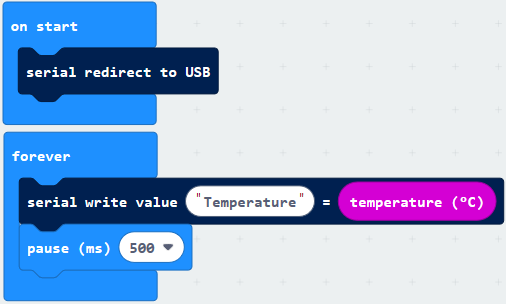
Click “Advanced” → ”Serial” → “serial redirect to USB” into “on start”.
*****************************************************************
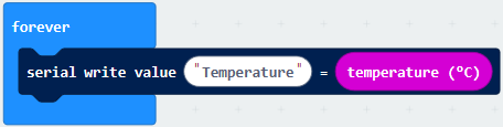
Go to “Serial” → “serial write value “x”=0” into “forever”
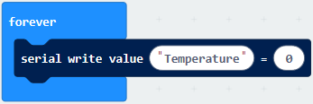
Click “Input” → “temperature(℃)” into “serial write value“x”=0 and change”0”into “temperature”
*****************************************************************
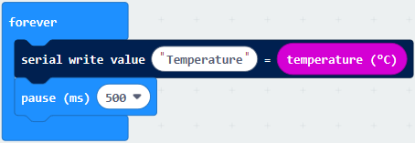
Go to“Basic”→“pause (ms) 100”into “forever”and set pause to 500
*****************************************************************
Complete Program:
|
①In“on start”the program only runs once; |
|---|---|
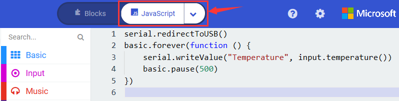
Select“JavaScript” and“Python”to switch into JavaScript and Python language code:
Test Results 1:
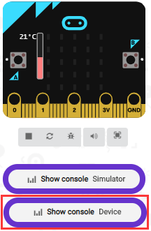
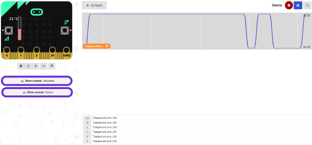
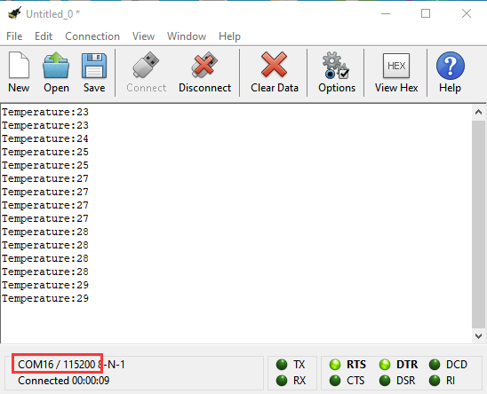
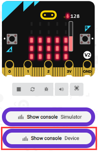
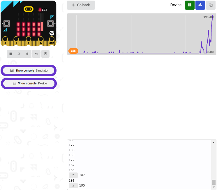
Uploading test code 1 to micro:bit main board V2, powering the main board via the USB cable, and clicking “Show console Device”, the data of temperature shows in the serial monitor page as shown below.
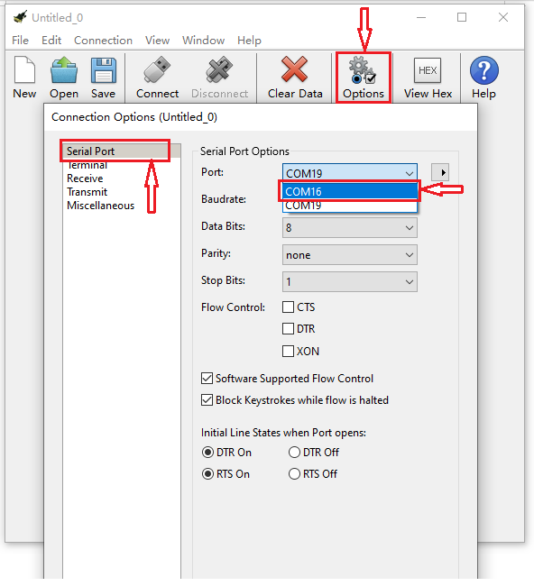
If you’re running Windows 7 or 8 instead of Windows 10, via Google Chrome won’t be able to match devices. You’ll need to use the CoolTerm serial monitor software to read data.
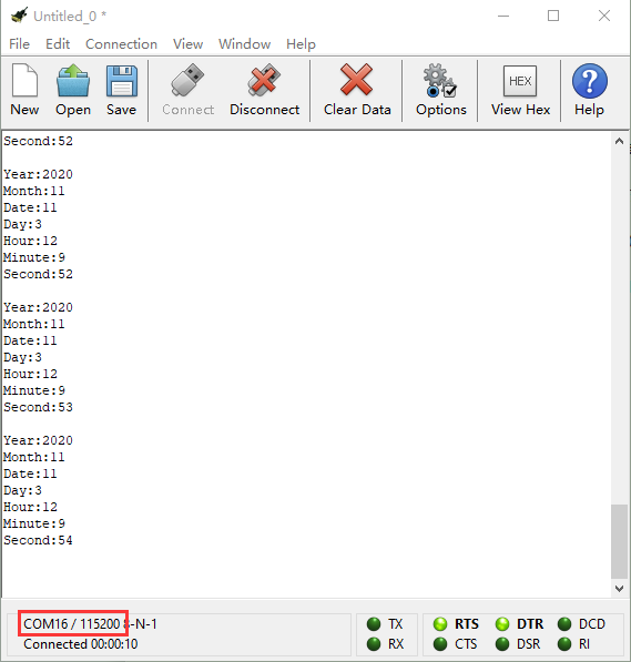
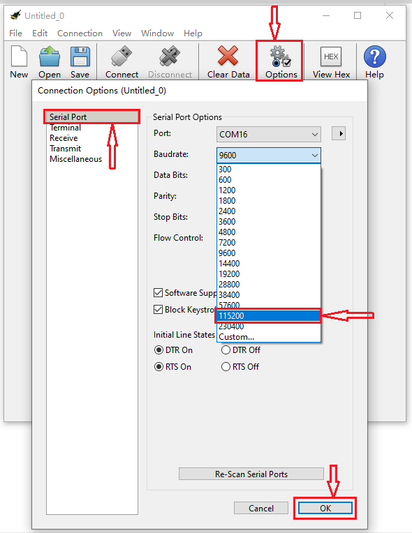
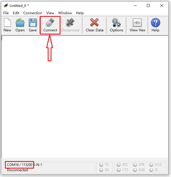
You could open CoolTerm software, click Options, select SerialPort, set COM port and baud rate to 115200 (after testing, the baud rate of USB SerialPort communication on Micro: Bit main board V2 is 115200), click OK, and Connect. The CoolTerm serial monitor shows the change of temperature in the current environment, as shown in the figures below :
Test Code 2:
Link computer with micro:bit board by micro USB cable, and program in MakeCode editor,
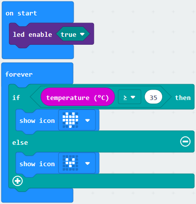
A. Go to“Led”→“more”→“led enable false”block,
B. Keep it into the“on start”block,tap the triangle button to select“true”.
*****************************************************************
Tap “Logic” and drag “if…then…else” into “forever” block; and then drag “=” into “true”
Enter “Input” to move “temperature(℃)” into the left side of “=”; click the little triangle of “=” to choose “≥”, and change the “0” to “35”
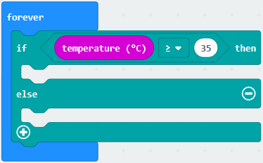
Click“Basic”to find out block“show icon”and move it into“then”; copy and place the block“show icon”to “else”and click the little triangle of “ ”to select “
 ”
”
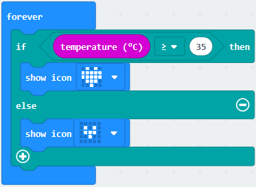
Complete Program:
|
①In“on start”the program only runs once; |
|---|---|
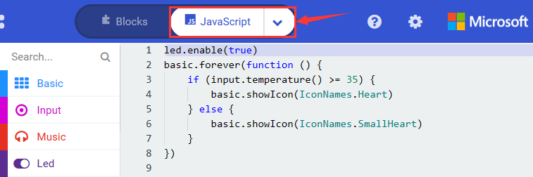
Select“JavaScript” and“Python”to switch into JavaScript and Python language code:
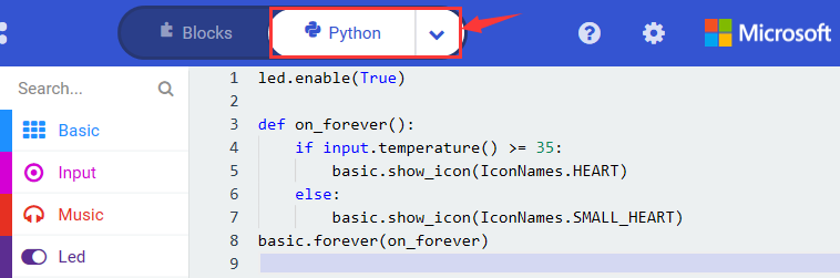
Test Results 2:
Uploading the code 2, when the ambient temperature is less than 35℃, 5*5LED will show . When the temperature is equivalent to or greater than 35℃, the pattern
 will appear.
Project 6: Geomagnetic Sensor
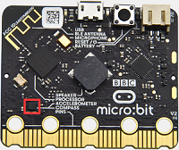
Project Description:
This project aims to explain the use of the Micro: bit geomagnetic sensor, which can not only detect the strength of the geomagnetic field, but also be used as a compass to find bearings. It is also an important part of the navigation attitude reference system (AHRS). Micro: Bit main board V2 uses LSM303AGR geomagnetic sensor, and the dynamic range of magnetic field is ±50 gauss. In the board, the magnetometer module is used in both magnetic detection and compass. In this experiment, the compass will be introduced first, and then the original data of the magnetometer will be checked.
The main component of a common compass is a magnetic needle, which can be rotated by the geomagnetic field and point toward the geomagnetic North Pole (which is near the geographic South Pole) to determine direction.
Components Needed:
Micro:bit main board V2 *1
Micro USB cable*1
Test Code 1:
Link computer with micro:bit board by micro USB cable, and program in MakeCode editor.
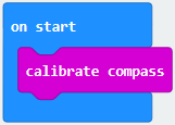
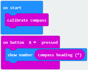
A. Click“Input”→“more”→“calibrate compass”
B. Lay down it into block“on start”.
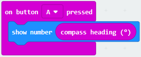
A. Go to“Input”→“on button A pressed”.
B. Enter“Basic”→“show number”, put it into“on button A pressed”block;
C. Tap“Input”→“compass heading(℃)”, and place it into“show number”
*****************************************************************
Complete Program:
|
①“on start”: command block only runs once to start program. |
|---|---|
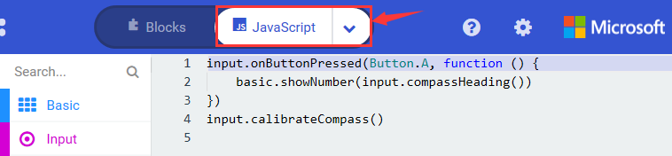
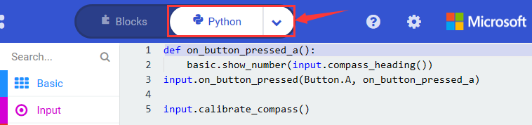
Select“JavaScript” and“Python”to switch into JavaScript and Python language code:
Test Results 1:
Uploading test code to micro:bit main board V2 and powering the board via the USB cable, and pressing the button A, the board asks us to calibrate compass and the LED dot matrix shows “TILT TO FILL SCREEN”. Then enter the calibration page. Rotate the board until all 25 LEDs are on red as shown below.
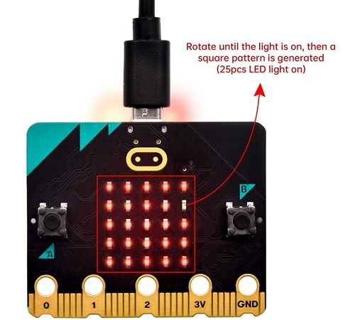
After that, a smile pattern  appears, which implies the calibration is done. When the calibration process is completed, pressing the button A will make the magnetometer reading display directly on the screen. And the direction north, east, south and west correspond to 0°, 90°, 180° and 270°.
Test Code 2:
This module can keep readings to determine direction, so does point to the current magnetic North Pole by arrow.
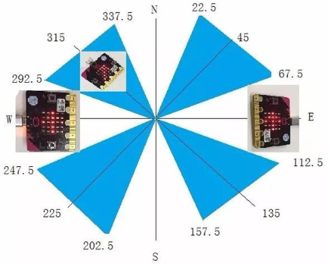
For the above picture, the arrow pointing to the upper right when the value ranges from 292.5 to 337.5. 0.5 can’t be input in the code, thereby, the values we get are 293 and 338.
Link computer with micro:bit board by micro USB cable, and program in MakeCode editor,
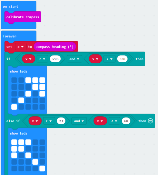
Enter“Input”→ “more”→“calibrate compass”. Move“calibrate compass”into“on start”
*****************************************************************
A. Click“Variables”→“Make a Variable…”→“New variable name:”
B. Input“x”in the blank box and click“OK”, and the variable “x” is generated.
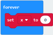
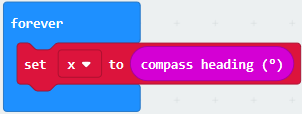
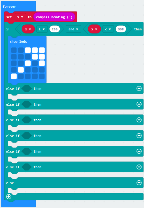
C. Drag out“set x to”into“forever”block
Go to“Input”→“compass heading(℃)”, and keep it into“0”box
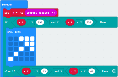
Tap“Logic”→“if…then…else”, leave it below block“sex x to compass heading”, then click icon for 6 times.
*****************************************************************
A. Place“and”into“true”block
B. Then move“=”block to the left box of “and”
C. Click“Variables”to drag“x”to the left “0”box, change 0 into 293 and set to “≥”;
D. Then copy“x≥293”once and leave it to the right “0”box and set to“x<338”

*****************************************************************
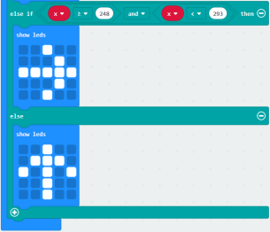
A. Go to“Basic”→“show leds”
B. Lay it down beneath  block,
then click“show leds”and the pattern
block,
then click“show leds”and the pattern  appears.
A. Duplicate for 6 times.
B. Separately leave them into the blank boxes behind “else if”.
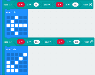
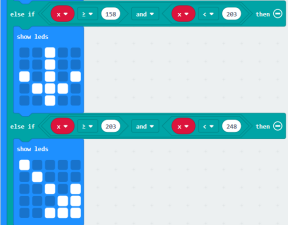
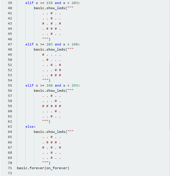
C. Set to“x≥23 and x<68”,“x≥68 and x<113 ”,“x≥113 and x<158 ”,“x≥158 and x<203 ”,“x≥203 and x<248 ”,“x≥248 and x<293 ”respectively.
D. Then copy “show leds”for 7 times and keep them below the “else if…….then” block respectively.
E. Click the blue boxes to form the pattern“ ”, “
”, “ ”, “
”, “ ”, “
”, “ ”, “
”, “ ”, “
”, “ ”and “
 ”.
”.
*****************************************************************************
Complete Program:
|
“on start”: command block only runs once to start program. |
|---|---|
 appears on the dot matrix
 is displayed on dot matrix
 is shown on dot matrix
 pattern appears


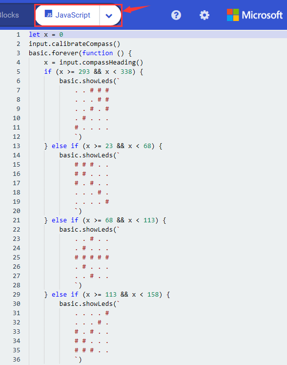
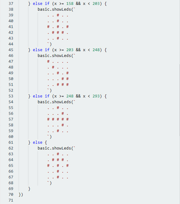
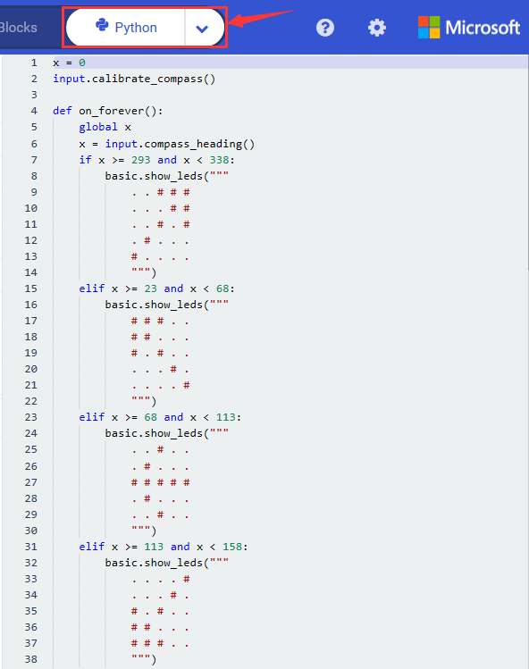
Select“JavaScript” and“Python”to switch into JavaScript and Python language code:
Test Results 2:
Upload code 2 and plug micro:bit to power. After calibration, tilt micro:bit board, the LED dot matrix displays the direction signs.
Project 7: Accelerometer
Project Description:
The Micro: Bit main board V2 has a built-in LSM303AGR gravity acceleration sensor, also known as accelerometer, with a resolution of 8/10/12 bits. The code section sets the range to 1g, 2g, 4g, and 8g.
We often use accelerometer to detect the status of machines.
In this project, we will introduce how to measure the position of the board with the accelerometer. And then have a look at the original three-axis data output by the accelerometer.
Components Needed:
Micro:bit main board V2 *1
Micro USB cable*1
Test Code 1:
Link computer with micro:bit board by micro USB cable, and program in MakeCode editor,
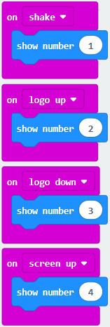
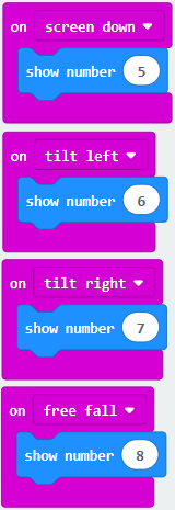
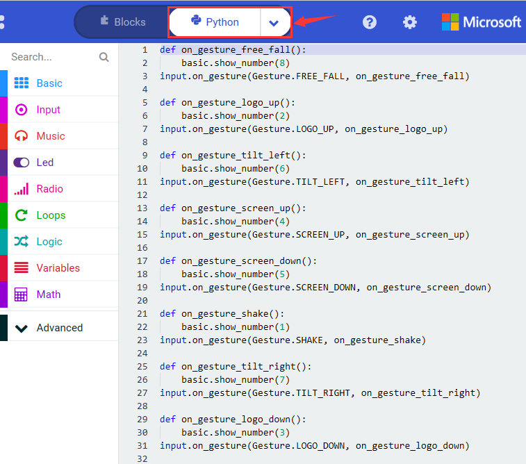
(1) A. Enter“Input”→“on shake”,
B. Click“Basic”→“show number”, place it into“on shake”block, then change 0 into 1.

*****************************************************************
(2) Copy code string for 7 times; separately click the triangle button to select“logo up”,“logo down”,“screen up”,“screen down”,“tilt left”,“tilt right”and“free fall”, then respectively change 1 into 2, 3, 4, 5, 6, 7, 8.
*****************************************************************
Complete Program:
|
Shake the Micro:bit board |
|---|---|
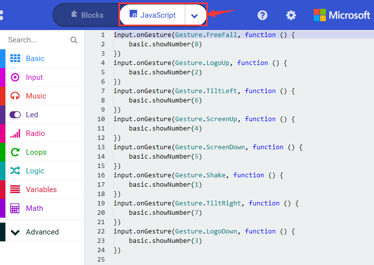
Select“JavaScript” and“Python”to switch into JavaScript and Python language code:
Test Results 1:
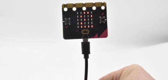
Uploading the test code 1 to micro:bit main board V2 and powering the board via the USB cable, if we shake the Micro: Bit main board V2. no matter at any direction, the LED dot matrix displays the digit “1”.
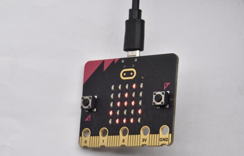
When it is kept upright (its logo above the LED dot matrix), the number 2 will show.

When it is kept upside down( its logo below the LED dot matrix) , it will show as below.
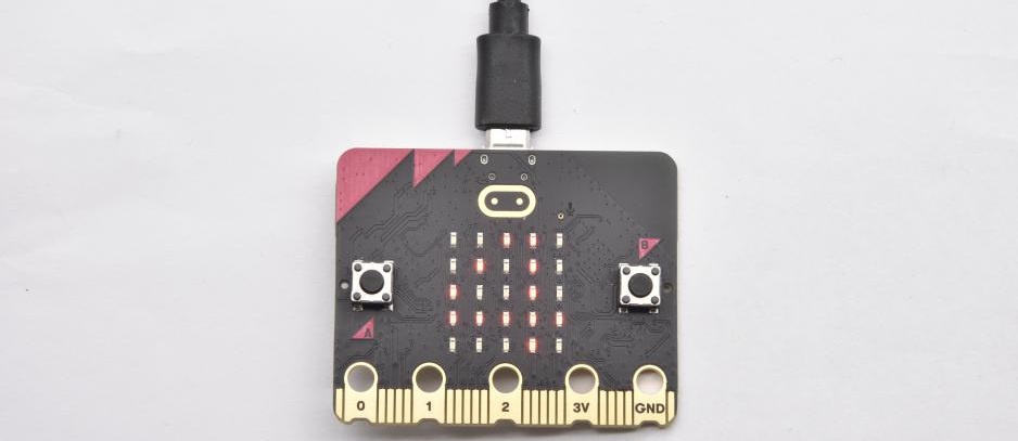
When it is placed still on the desk, showing its front side, the number 4 appears.
When it is placed still on the desk, showing its back side, the number 5 will exhibit.
When the board is tilted to the left , the LED dot matrix shows the number 6 as shown below.
When the board is tilted to the right , the LED dot matrix displays the number 7 as shown below
When the board is knocked to the floor, this process can be considered as a free fall and the LED dot matrix shows the number 8. (please note that this test is not recommended for it may damage the main board.)
Attention: if you’d like to try this function, you can also set the acceleration to 3g, 6g or 8g. But still ,we don not recommend.
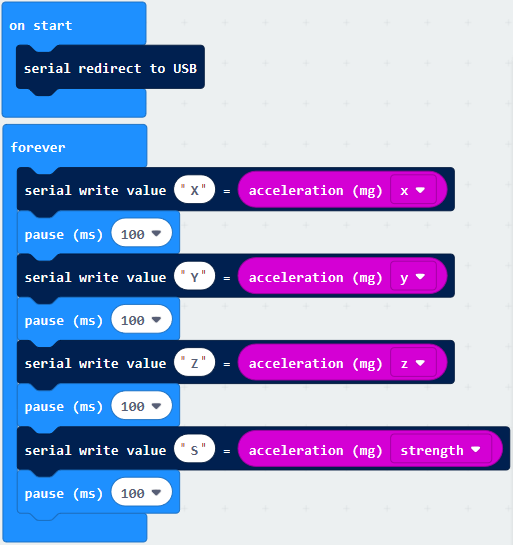
Test Code 2:
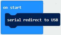
A. Go to“Advanced”→“Serial”→“serial redirect to USB”
B. Drag it into“on start”
*****************************************************************
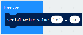
A. Enter“Serial”→“serial write value x =0”
B. Leave it into“forever”block
*****************************************************************
A. Click“Input”→“acceleration(mg) x”;
B. Keep it into“0”box and capitalize the“x”
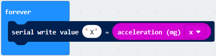
*****************************************************************
Go t“Basic”and move out“pause (ms) 100”below the block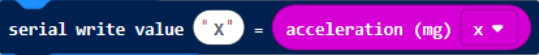 , then set to 100ms.
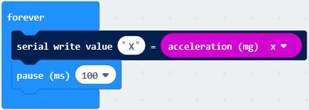
*****************************************************************
Replicate code string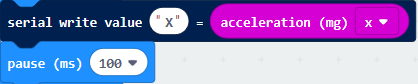 for 3 times and keep them into“forever”block,separately set the whole code string as follows:
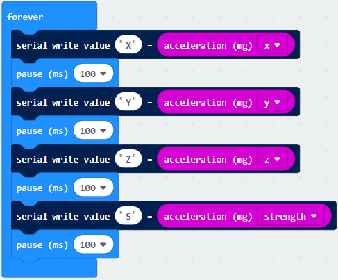
Complete Program:
|
“on start”: |
|---|---|
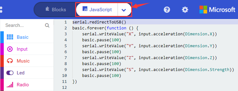
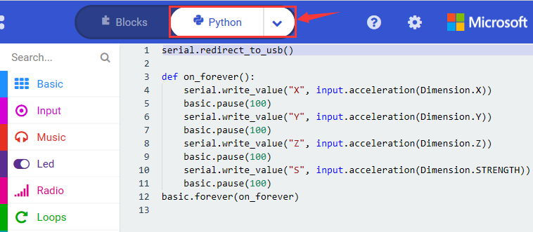
Select“JavaScript” and“Python”to switch into JavaScript and Python language code:
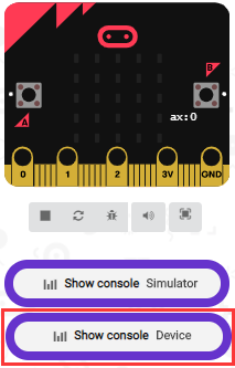
Test Results 2:
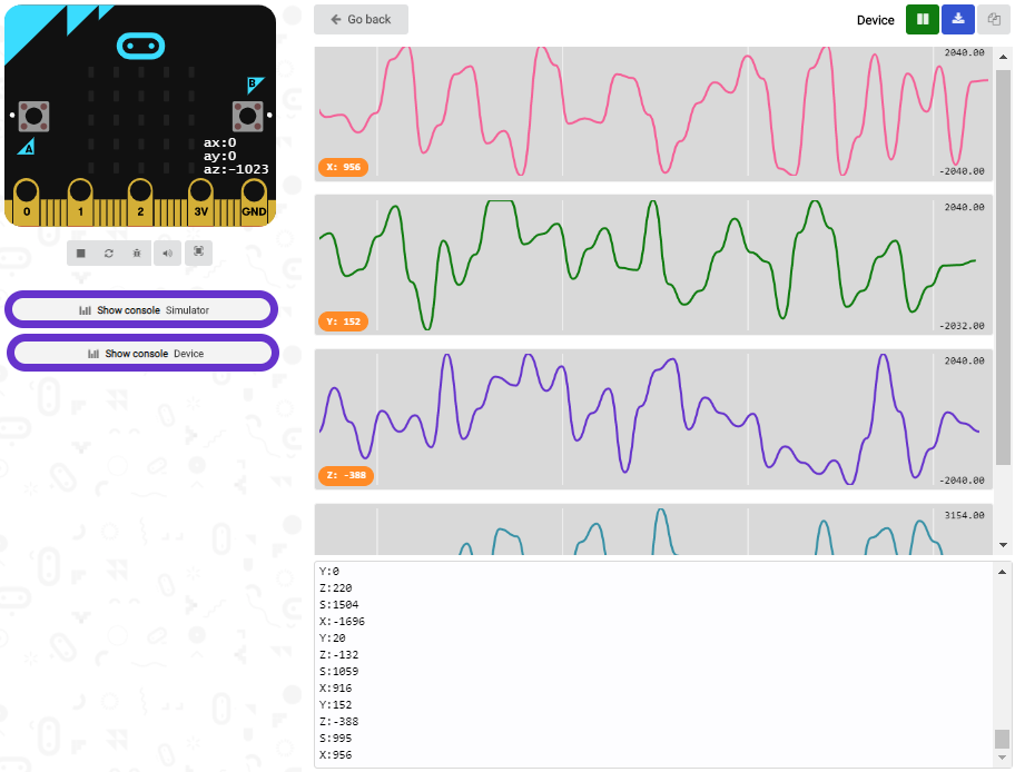
Upload test code to micro:bit main board V2, power the main board via the USB cable, and click “Show console Device”.
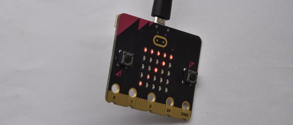
After referring to the MMA8653FC data manual and the hardware schematic diagram of the Micro: Bit main board V2, the accelerometer coordinate of the Micro: Bit V2 motherboard are shown in the figure below:
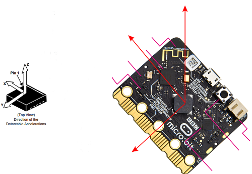
The following interface shows the decomposition value of acceleration in X axis, Y axis and Z axis respectively, as well as acceleration synthesis (acceleration synthesis of gravity and other external forces).
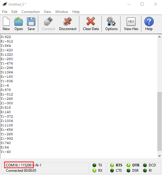
If you’re running Windows 7 or 8 instead of Windows 10, via Google Chrome won’t be able to match devices. You’ll need to use the CoolTerm serial monitor software to read data.
You could open CoolTerm software, click Options, select SerialPort, set COM port and baud rate to 115200 (after testing, the baud rate of USB SerialPort communication on Micro: Bit main board V2 is 115200), click OK, and Connect. The CoolTerm serial monitor shows the data of X axis, Y axis and Z axis , as shown in the figures below :
Project 8: Light Detection
Project Description:
In this project, we focus on the light detection function of the Micro: Bit main board V2. It is achieved by the LED dot matrix. And it can be viewed as a photosensor.
Components Needed:
Micro:bit main board V2 *1
Micro USB cable*1
Test Code:
Link computer with micro:bit board by micro USB cable, and program in MakeCode editor,
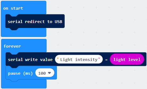
(1)A. Enter“Advanced”→“Serial”→“serial redirect to USB”;
B. Drag it into“on start”block.
*****************************************************************
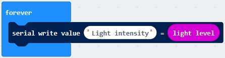
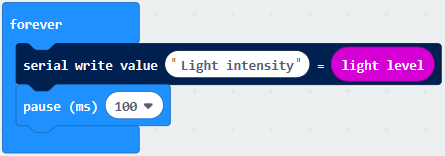
(2) A. Go to“Serial”→“serial write value x =0”;
B. Move it into“forever”
A. Click“Input”→“acceleration(mg) x”
B. Put“acceleration(mg) x”in the“0”box and change “x”into“Light intensity”.
*****************************************************************
A. Click“Basic”→“pause (ms) 100”;
B. Lay it down into“forever”and set to 100ms.
*****************************************************************
Complete Program:
|
“on start”: |
|---|---|
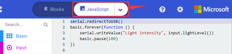
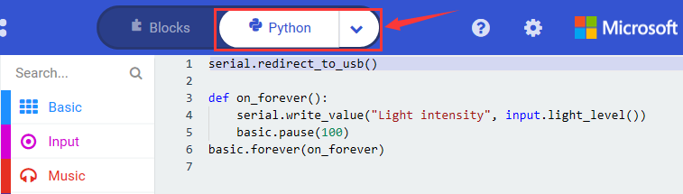
Select“JavaScript” and“Python”to switch into JavaScript and Python language code:
Test Results:
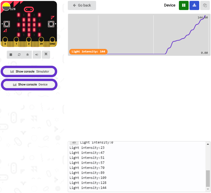
Upload the test code to micro:bit main board V2, power the board via the USB cable and click“Show console Device”.
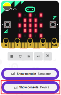
When the LED dot matrix is covered by hand, the light intensity showed is approximately 0; when the LED dot matrix is exposed to light,the light intensity displayed gets stronger with the light as shown below.
The 20 in the code is an arbitrary value of light intensity. If the current light level is less than or equal to 20, the moon will appear on the LED dot matrix. If it’s bigger than 20, the sun will appear.
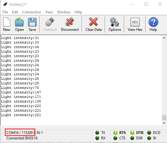
If you’re running Windows 7 or 8 instead of Windows 10, via Google Chrome won’t be able to match devices. You’ll need to use the CoolTerm serial monitor software to read data.
You could open CoolTerm software, click Options, select SerialPort, set COM port and baud rate to 115200 (after testing, the baud rate of USB SerialPort communication on Micro: Bit main board V2 is 115200), click OK, and Connect. The CoolTerm serial monitor shows the value of light intensity , as shown in the figures below :
Project 9: Speaker
Project Description:
The Micro: Bit main board V2 has an built-in speaker, which makes adding sound to the programs easier. We can program the speaker to air all kinds of tones .
Components Needed:
Micro:bit main board V2 *1
Micro USB cable*1
Test Code:
Link computer with micro:bit board by micro USB cable, and program in MakeCode editor,
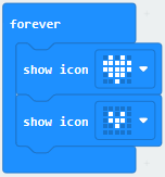
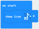
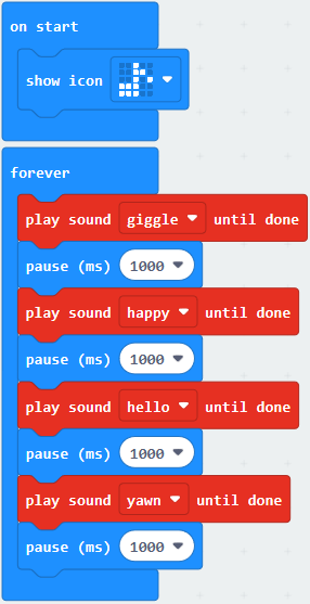
(1) Enter“Basic”module to find “show icon”and drag it into “on start”block;
Click the little triangle to find “ ”
”
*****************************************************************
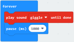
(2) Enter“Music”module to find and drug“play sound giggle until done”into“forever”block;
Enter“Basic”module to find and drug“pause(ms) 100” into“forever”block ;
Change 100 into 1000;
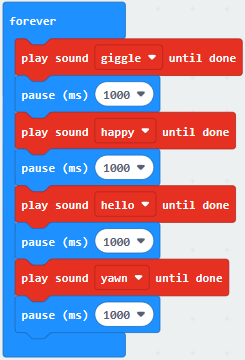
( 3 ) Copy 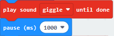 three times and place it into “forever” block ;
Click the little triangle to select“happy”,”hello”,”yawn”;
************************************************************
Complete Program:
|
①In “on start”the program only runs once; |
|---|---|
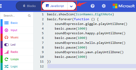
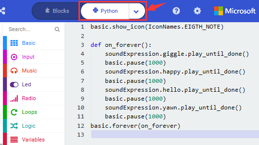
Select “JavaScript” and “Python” to switch into JavaScript and Python language code:
Test Results:
Uploading the test code to micro:bit main board V2 and powering the board via the USB cable, the speaker utters sound and the LED dot matrix shows the logo of music.
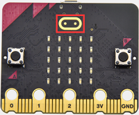
Project 10: Touch-sensitive Logo
Project Description:
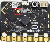
The Micro: Bit main board V2 is equipped with a golden touch-sensitive logo, which can act as an input component and function like an extra button.
It contains a capacitive touch sensor that senses small changes in the electric field when pressed (or touched), just like your phone or tablet screen do.When you press it , you can activate the program.
Components Needed:
Micro:bit main board V2 *1
Micro USB cable*1
Test Code:
Link computer with micro:bit board by micro USB cable, and program in MakeCode editor,
( 1 ) Delete block“on start”and“forever”;
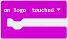
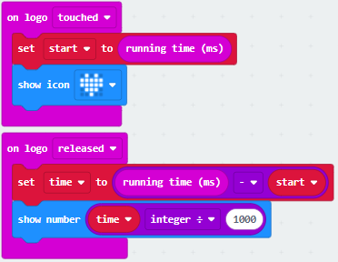
( 2 )Enter“Input”module to find and drag“on logo pressed” ; Click the little triangle to find “touched”’;
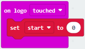
( 3 ) Enter module“Variables”→choose“Make a Variable”→input “start”→click“OK”
The variable“start”is established;
Enter“Variables”module to find and drag“set start to 0”into“on logo touched”block;
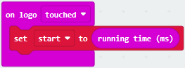
( 4 )Enter“Input”module →click“more”→ find and drag“running time(ms)”into the“0”of“set start to 0”block;
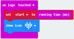
( 5 )Enter“Basic”module to find and drag“show icon” into “on logo touched”block;
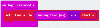
( 6 )Enter“Input”module to find and drag“on logo pressed”→choose “released”→ establish variable “time”;
( 7 )Enter“Variables”module to find and drag “set time to 0”into “on logo pressed”block;
( 8 )Enter“Math”module to find and drag “0-0”into the “0”of“set start to 0”block;
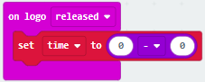
( 9 )Enter“Input”module→ “more” → find and drag “running time(ms) into“0”on the left side of “0-0”;
( 10 )Enter“Variables”module to find and drag“start” into “0”on the right side of “0-0”;
( 11 )Enter“Basic”module to find and drag“show number” into “on logo released”block;
( 12 )Enter“Math”module to find and drag“square root 0” into “0”;
( 13 )Click the little triangle to find”integer÷”;
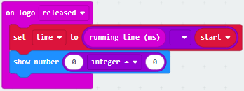
( 14 )Enter“Variables”module to find and drag“time”into“0”on the left side of“0-0”and change the“0”on the right side to“1000”;
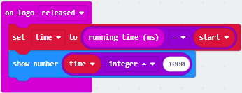
Complete Program:
|
①Touch the logo on the micro:bit with hand; |
|---|---|
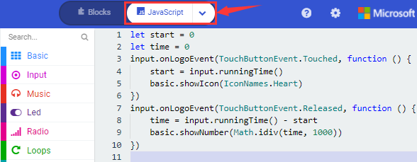
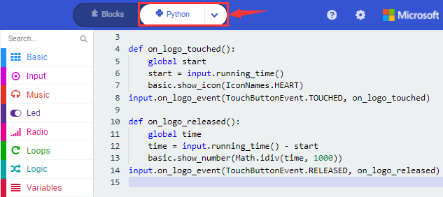
Select “JavaScript” and “Python” to switch into JavaScript and Python language code:
Test Results:
Uploading the test code to micro:bit main board V2 and powering the board via the USB cable, the LED dot matrix exhibits the heart pattern when the touch-sensitive logo is pressed or touched and displays digit when the logo is released.
Project 11: Microphone
Project Description:
The Micro: Bit main board V2 is built with a microphone which can test the volume of ambient environment. When you clap, the microphone LED indicator will turn on. Since it can measure the intensity of sound, you can make a noise scale or disco lighting changing with music. The microphone is placed on the opposite side of the microphone LED indicator and in proximity with holes that lets sound pass.When the board detects sound, the LED indicator lights up.
Components Needed:
Micro:bit main board V2 *1
Micro USB cable*1
Test Code 1:
Link computer with micro:bit board by micro USB cable, and program in MakeCode editor,
Delete block“on start”and“forever”;
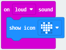
Enter“Input”module to find and drag“on loud sound”;
Enter“Basic”module to find and drag “show number”into “on loud sound”block ;
************************************************************
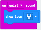
Copy 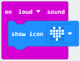 once;
once;
Click the little triangle of “lond” to choose”quiet”;
Click the little triangle of “” to choose” ”;
”;
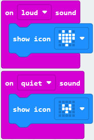
Complete Program:
|
①The microphone on the micro:bit detects sound; |
|---|---|
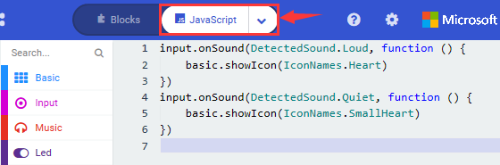
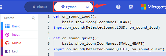
Select “JavaScript” and “Python” to switch into JavaScript and Python language code:
Test Results 1:
Uploading test code to micro:bit main board V2 and powering the board via the USB cable, the LED dot matrix displays pattern “”when you claps and pattern when it is quiet around.
Test Code 2:
Link computer with micro:bit board by micro USB cable, and program in MakeCode editor,
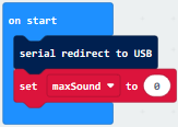
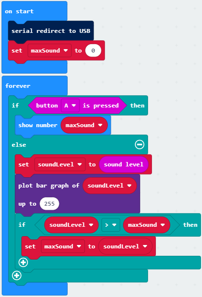
Enter“Advanced”module→ choose“Serial”to find and drag“serial redirect to USB”into “on start”block ;
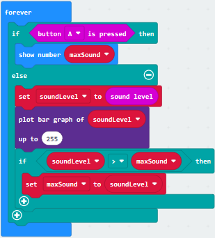
Enter“Variables”module→ choose“Make a Variable”→ input“maxSound”→click “OK”,variable ”maxSound”is established;
Enter“Variables”module to find and drag“set maxSound to 0”into “on start”block ;
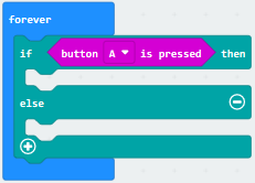
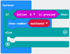
Enter“Logic”module to find and drag“if true then…else”into“forever” block ;
Enter“Input”module to find and dragbutton A is pressed”into“then” ;
Enter“Basic”module to find and drag“show number”into “then” ;
Enter“Variables”module to find and drag“maxSound”into“0” ;
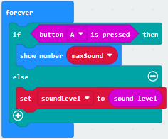
Establish variable“soundLevel”;
Enter“Variables”module to find and drag“set soundLevel to 0”into “else”;
Enter“Input”module to find and drag“sound level”into“0”;
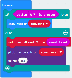
Enter“Led”module to find and drag“plot bar graph of 0 up to 0” into “else”;
Enter“Variables”module to find and drag“soundLevel”into the“0”behind “of”;
Change the“0”behind“up” to“255”;
Enter“Logic”module to find and drag“if true then”into “else”block ;
Enter“Logic”module to find and drag“0 > 0”into“then”;
Enter“Variables”module to find and drag“soundLevel”into“0”on the left side of“0-0” ;
Enter“Variables”module to find and drag“maxSound”into“0”on the right side;
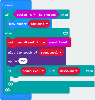
Enter“Variables”module to find and drag“set maxSound to 0”into the second “then”;
Enter“Variables”module to find and drag“soundLevel”into the “0” ;
Complete Program:
|
①In “on start” the program only runs once; |
|---|---|
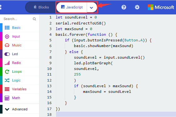
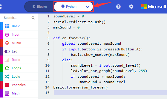
Select “JavaScript” and“Python”to switch into JavaScript and Python language code:
Test Results 2:
Upload test code to micro:bit main board V2, power the board via the USB cable and click “Show console Device”as shown below.
When the sound is louder around, the sound value shows in the serial port is bigger as shown below.
What’s more, when pressing the button A, the LED dot matrix displays the value of the biggest volume( please note that the biggest volume can be reset via the Reset button on the other side of the board ) while when clapping, the LED dot matrix shows the pattern of the sound.
Project 12: Bluetooth Wireless Communication
Project Description:
The Micro: Bit main board V2 comes with a nRF52833 processor (with built-in Bluetooth 5.1 BLE(Bluetooth Low Energy) device) and a 2.4GHz antenna for Bluetooth wireless communication and 2.4GHz wireless communication. With the help of them, the board is able to communicate with a variety of Bluetooth devices, including smart phones and tablets.
In this project, we mainly concentrate on the Bluetooth wireless communication function of this main board. Linked with Bluetooth, it can transmit code or signals. To this end, we should connect an Apple device (a phone or an iPad) to the board.
Since setting up Android phones to achieve wireless transmission is similar to that of Apple devices, no need to illustrate again.
Preparation:
*Attach the Micro:bit main board V2 to your computer via the Micro USB cable.
*An Apple device (a phone or an iPad) or an Android device;
Procedures:
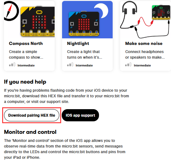
For Apple devices, enter this link: https://www.microbit.org/get-started/user-guide/ble-ios/ with your computer first, and then click “Download pairing HEX file”to download the Micro: Bit firmware to a folder or desk, and upload the downloaded firmware to the Micro: Bit main board V2.
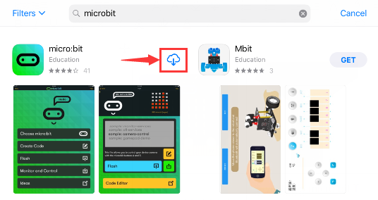
Search“micro bit”in your App Store to download the APP micro:bit.
Wirelessly connect your iOS device to the micro: bit board V2:
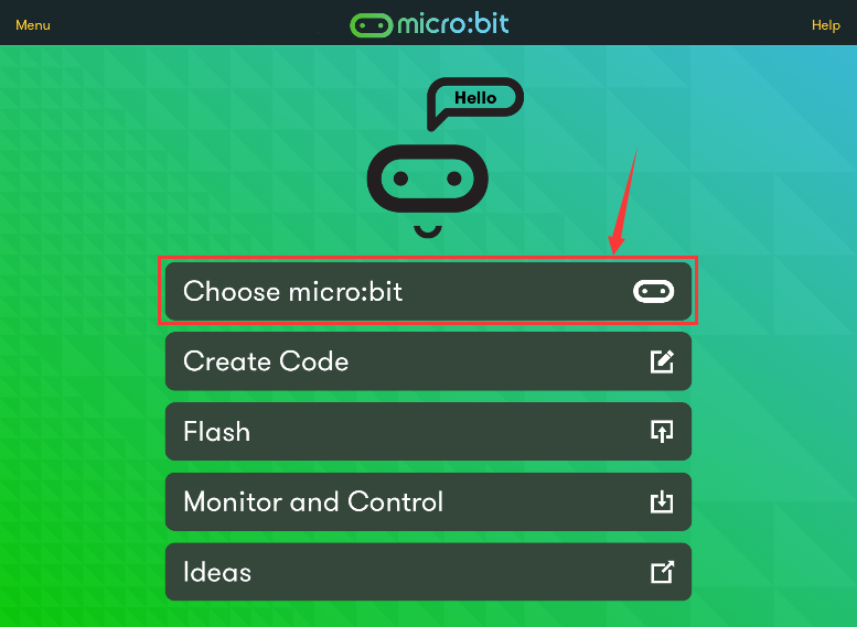
Firstly, turn on the Bluetooth of your iOS device and open
Please make sure that the Micro: Bit main board V2 and your computer are still linked via the USB cable.
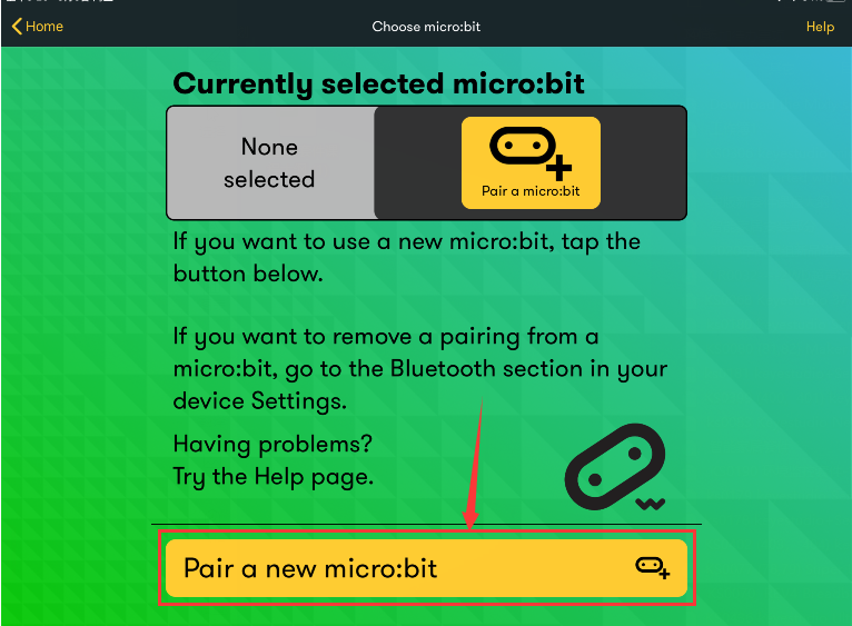
Select“Choose micro:bit”to start pairing Bluetooth.
Secondly, click “Pair a new micro:bit”;
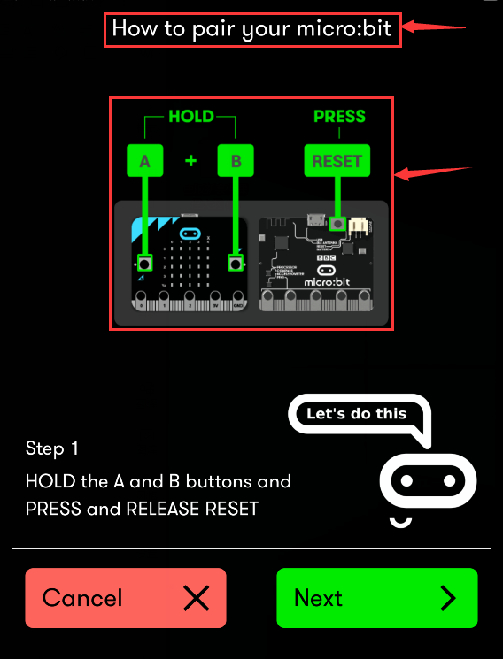
Following the instructions to press button A and B at the same time(do not release them until you are told to) and press Reset & Power button for a few seconds.
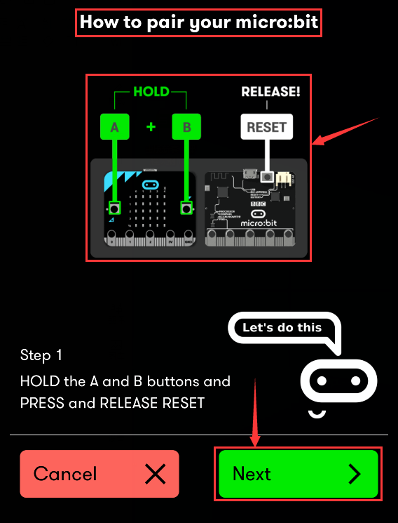
Release the Reset & Power button, you will see a password pattern shows on the LED dot matrix. Now , release buttons A and B and click Next.
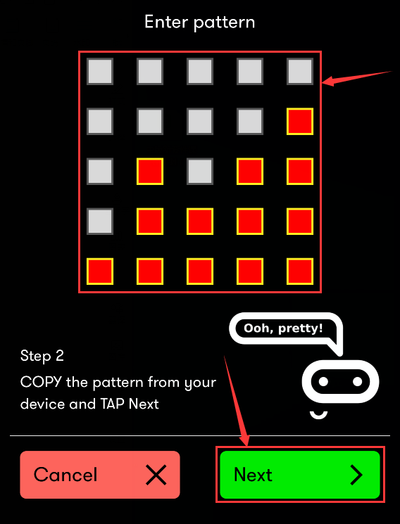
Set the password pattern on your Apple device as the same pattern showed on the matrix and click Next.
Still click Next and a dialog box props up as shown below. Then click “Pair”. A few seconds later, the match is done and the LED dot matrix displays the “√” pattern.
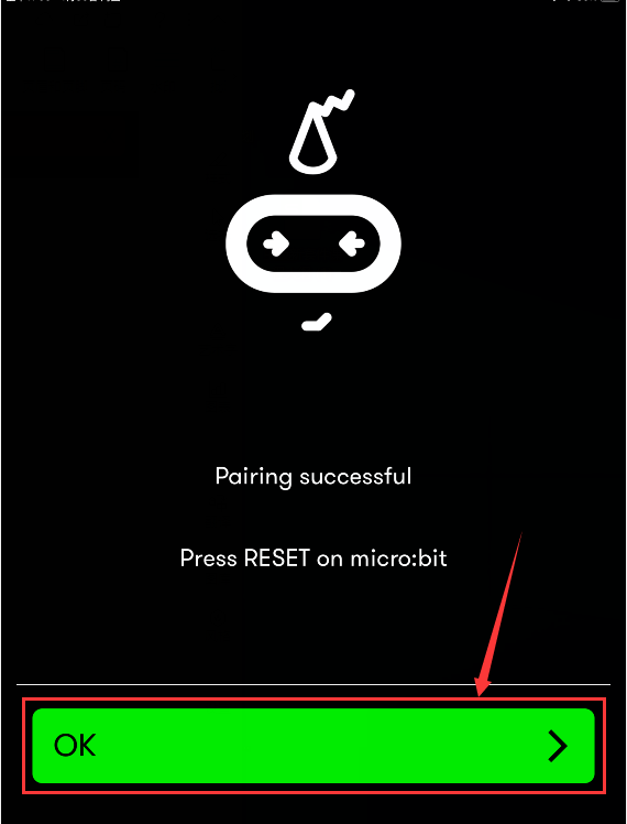
After the match with Bluetooth, write and upload code with the App.
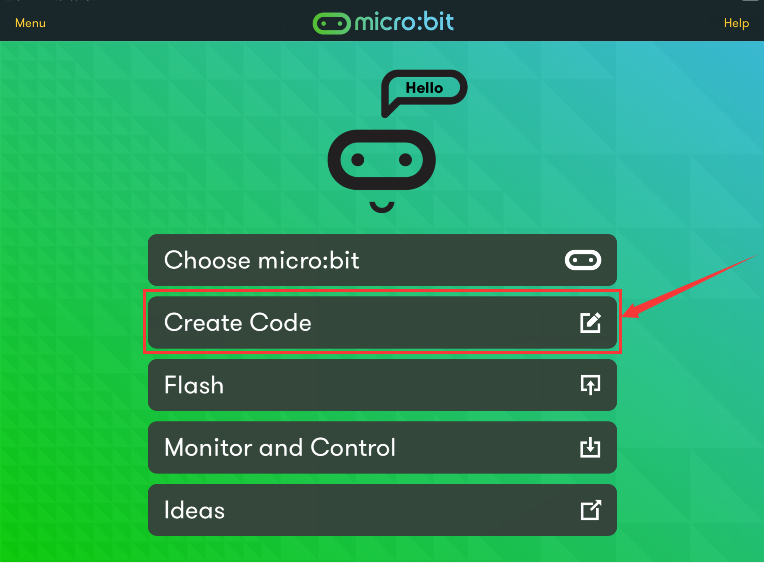
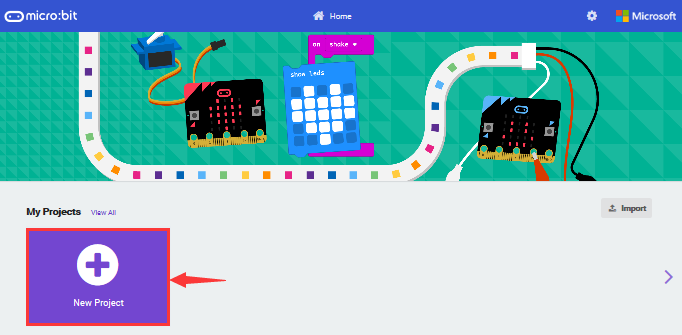
Click “Create Code” to enter the programming page and write code.
Click  and the box
 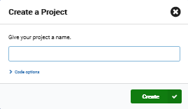 appears, and then select “Create √”.
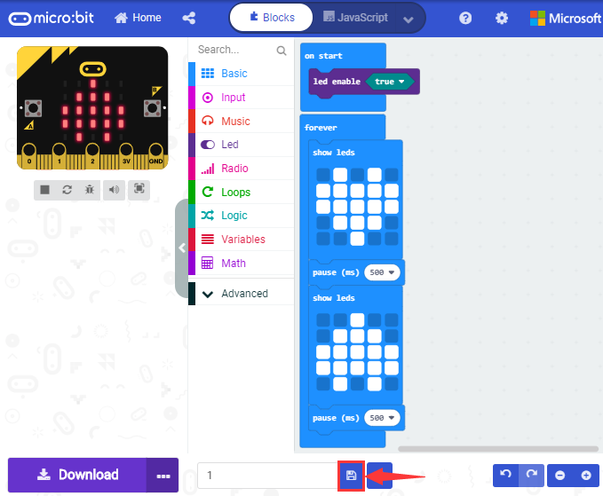
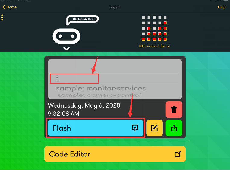
Name the code as “1 “and click  to save it.
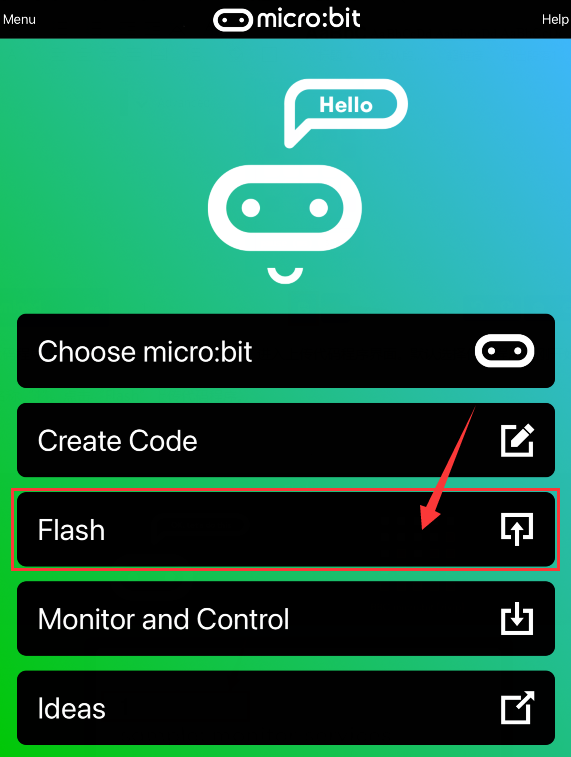
Click the third item“Flash”to enter the uploading page. The default code program for uploading is the one saved just now and named “1” and then click the other “Flash” to upload the code program “1”.
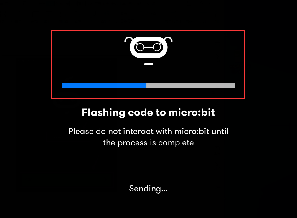
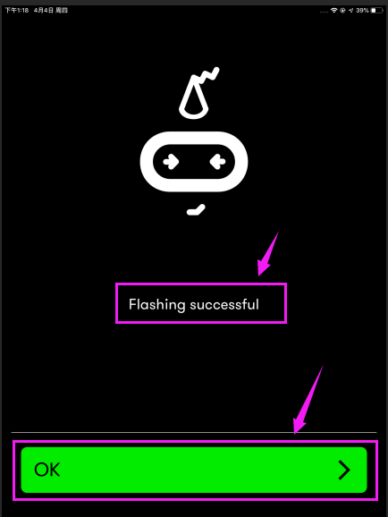
If the code is uploaded successfully a few seconds later, the App will emerge as below and the LED dot matrix of the Micro: Bit main board V2 will exhibit a heart pattern.
Projects below all conduct with the built-in sensors and the LED dot matrix while the following ones will carry out with the help of external sensors.
(Attention:to avoid burning the the Micro:bit main board V2, please remove the USB cable and the external power from the board before fix it with a T-shaped shield; likewise, the USB cable and the external power should be cut from the main board before disconnect the shield from the board.)
Project 13: LED Blink
Description:
LED blink is a basic experiment. You will learn how to make white LED blink through code. Please turn off dot matrix on micro:bit before testing.
What You Need:
Micro:bit Board*1
EASY Plug Shield for micro bit V1.1*1
Micro USB Cable*1
EASY Plug Yellow LED Module*1
RJ11 Cable*1
1-Slot AA Battery Holder*1
1.5V AA Battery*6
EASY Plug Yelow LED Module:
The LED light modules have shiny colors, ideal for Arduino starters. It can be easily connected to IO/Sensor shield.
Note: this module needs to be used together with EASY Plug Shield for micro bit V1.1. You can also choose other LED to emit different color of light like white, blue, green, yellow and red.
Specification:
Interface: Easy plug
Sensor type: Digital
Working voltage: 5V
LED color: yellow
Easy to use
Useful for light projects
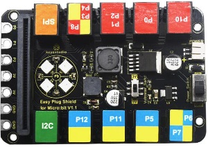
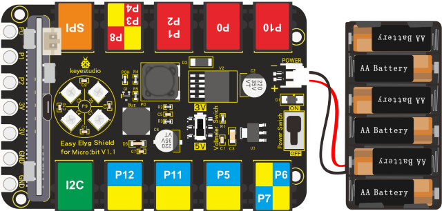
EASY Plug Shield for micro bit V1.1:
Micro:bit is a basic development board designed by the British Broadcasting Corporation for youth programming education. It supports the PXT graphical programming interface developed by Microsoft, without the need to download an additional compiler, and can be used under Windows, macOS, IOS, Android and other operating systems.
We combine EASY Plug shield with micro:bit due to the inconvenience of wiring up micro:bit .
The golden finger interfaces ,as well as 10 pcs easy plug ports (RJ11 6P6C interfaces)could be connected to other modules and sensors, therefore, you don’t need to worry about wiring up components incorrectly.
The shield comes with 4 pcs WS2812 LEDs controlled by P9, P0 controls passive buzzer; and two dial switches–Power_Switch and Voltmeter_Switch(3.3V, 5V).
The voltage of power supply is DC 6-10V.
The Easy Plug port only supports the sensors and modules with RJ11 6P6C port.
Specification:
Power supply: DC 6-10V
Output current: 1.5A
Interface: RJ11 6P6C interface and golden finger interface
Size: 98*65*17mm
Interface Description:
G:GND
V: Voltmeter_Switch control,dial to 5V end,5V;dial to 3V end, 3.3V
I2C Communication Port

SDA:P20
SCL:P19
SPI Communication Port

MOSI:P15
MISO:P14
SCK:P13
Wiring Up:
Insert micro:bit onto EASY Plug shield, link white LED module with P5 port of shield and plug in power.
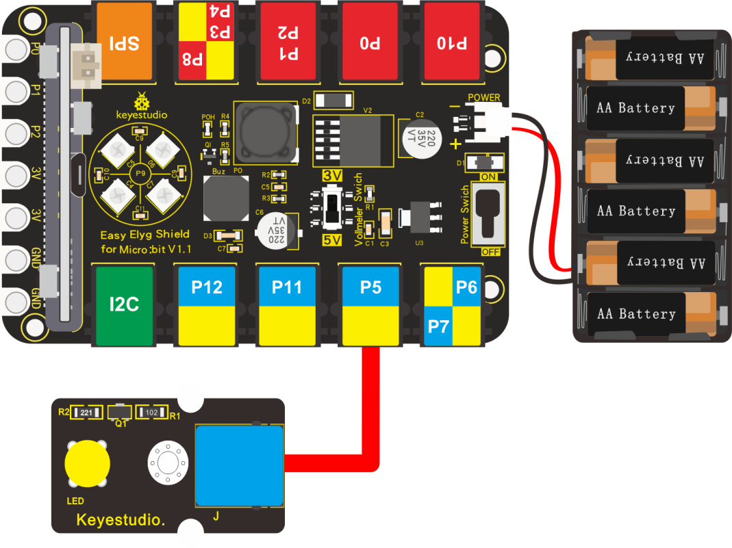
Note: Dial Voltmeter_Switch to 3V end.
Test Code:
You could navigate https://makecode.micro:bit.org/reference to have access to more details.
Browse link https://makecode.micro:bit.org/ to edit your program. The following test code is as for your reference.
|
“on start”: command block only runs once to start program. |
|---|---|
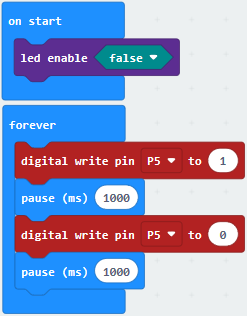
Test Results:
Wire up, dial Voltmeter_Switch to 5V end, plug in external power and dial Power_Switch to ON end. Upload code to micro:bit and you will view LED flashing, with interval of 1s.
Project 14: Breath
Description:
The light breath experiment is a little bit similar to the previous project. This time we connect the EASY Plug Red Led module to the EASY Plug Shield for micro bit V1.1. Connect the pin of LED module to P10 of micro:bit. From the Pinout diagram of micro:bit, you can get the P10 can be used as Analog IN.
This lesson you will learn how to control the brightness of LED on the module, gradually becoming brighter and dimming, just like the LED is breathing.
What You Need:
Micro:bit Board*1
EASY Plug Shield for micro bit V1.1*1
Micro USB Cable*1
EASY Plug Red LED Module*1
RJ11 Cable*1
6-Slot AA Battery Holder*1
1.5V AA Battery*6
Wiring Up:
Insert micro:bit onto EASY Plug shield, connect red LED module to P10 of shield with a RJ11 cable, and plug in external power.
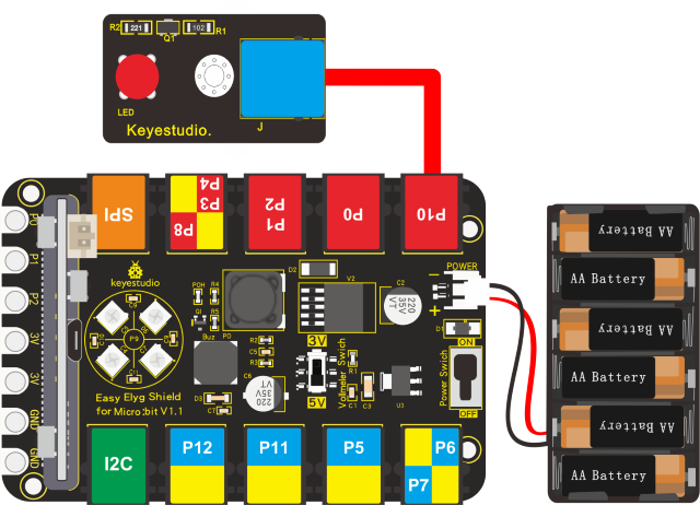
Note: Dial Voltmeter_Switch to 3V end
Test Code:
You could navigate https://makecode.micro:bit.org/reference to have access to more details.
Browse link https://makecode.micro:bit.org/ to edit your program. The following test code is as for your reference.
|
“on start”: command block only runs once to start program. |
|---|---|
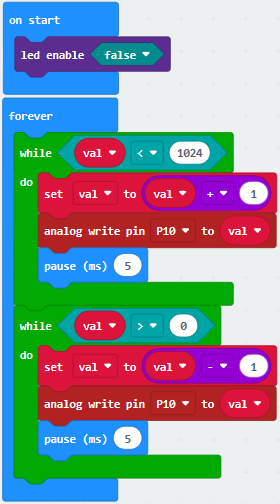
Test Results:
Wire up, dial Voltmeter_Switch to 3V end, plug in external power and dial Power_Switch to ON end and upload code to micro:bit.
You will find LED of module get brighter then darker, like human breath.
Project 15: Blink and Breath
Description:
In this project, we will combine LED flash and breathing effect together.
What You Need:
Micro:bit Board*1
EASY Plug Shield for micro bit V1.1*1
Micro USB Cable*1
EASY Plug Red LED Module*1
RJ11 Cable*1
6-Slot AA Battery Holder*11.5V AA Battery*6
Wiring Up:
Insert micro:bit onto EASY Plug shield,connect red LED module to P10 of shield with a RJ11 cable and connect external power.
Note: Dial Voltmeter_Switch to 3V end
Test Code:
You could navigate https://makecode.micro:bit.org/reference to have access to more details.
Browse link https://makecode.micro:bit.org/ to edit your program. The following test code is as for your reference.
|
“on start”: command block only runs once to start program. |
|---|---|
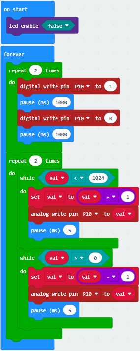
Test Results:
Wire up, dial Voltmeter_Switch to 3V end, plug in power and dial Power_Switch to ON end. Upload program to micro:bit, LED flashes twice and shows breathing effect twice ceaselessly.
Project 16: RGB
Description:
EASY Plug shield comes with 2812 2x2 full color RGB, we will finish three experiments with 2812 2x2 full color RGB.
In this project, we will demonstrate how to play music with passive buzzer. Easy Plug shield comes with one. Let’s get started. (Passive buzzer is connected to P9 on Easy Plug shield)
What You Need:
Micro:bit Board*1
EASY Plug Shield for micro bit V1.1*1
Micro USB Cable*1
6-Slot AA Battery Holder*1
1.5V AA Battery*6
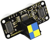
2812 2x2 full color RGB:
2812 2x2 full color RGB module is a smart external control LED light source that integrates control circuit and lighting circuit. Each LED has the same appearance as a 5050 LED bead, and each component is a pixel point.
The pixel point includes an intelligent digital interface data latch signal shaping and amplifying driving circuit, as well as a high-precision internal oscillator and a 12V high-voltage programmable constant current control part, which effectively ensures that the color of the pixel point light is highly uniform.
The data protocol adopts the single-line return-to-zero code communication mode. After power-on and reset the pixel point, the S pin receives the data transmitted from the controller. And the 24-bit data are extracted by the first pixel and then sent to the data latch inside the pixel point.
LED has advantages of low voltage drive, environmental protection and energy saving, high brightness, wide scattering angle, good consistency, ultra low power, long life and so on.
Specification:
Working voltage: DC 5V
Power: 0.1W
Light source: SMD 5050 RGB
IC model: 4pcs/WS2811
Gray level: 256 levels
Beam angle: 180°
Luminous color: can be adjusted to white, red, yellow, blue, green, etc. by the controller
Wiring Up:
Note: Dial Voltmeter_Switch to 3V end
Test Code:
You could navigate https://makecode.micro:bit.org/reference to have access to more details.
Browse link https://makecode.micro:bit.org/ to edit your program. The following test code is as for your reference.
We need to set test code in library file, and add the library of “neopixe”.
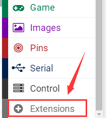
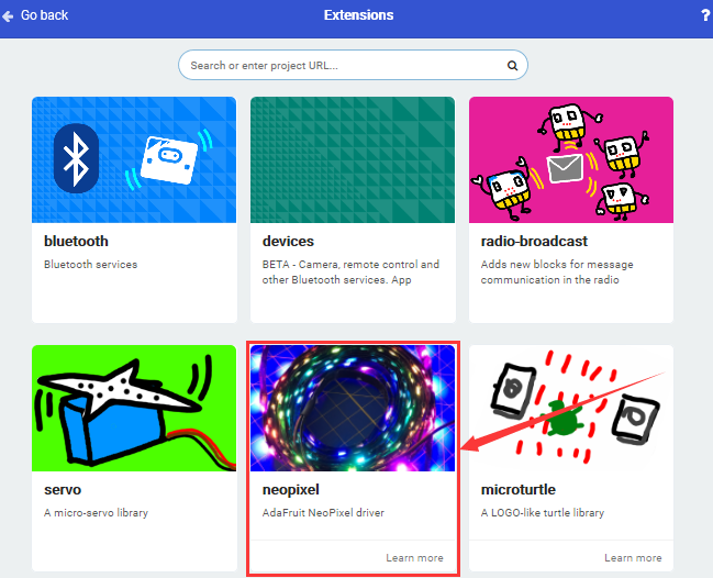
Click“Extensions”→“neopixel”,click to download
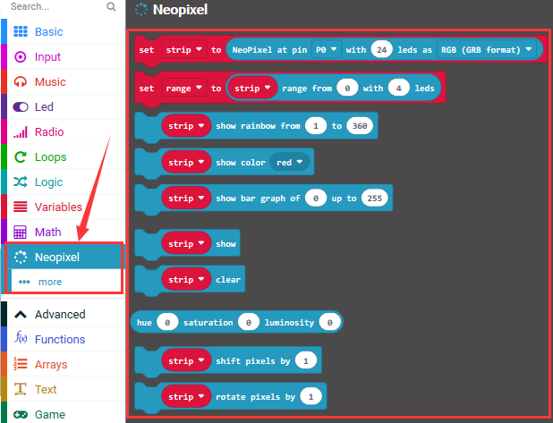
You will view library“neopixel”in the editing blocks, as shown below:
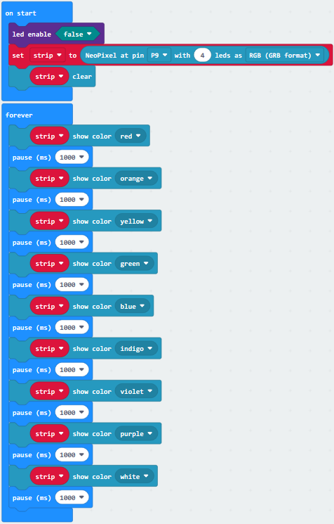
Code 1:
|
“on start”: |
|---|---|
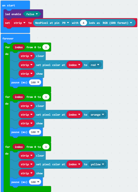
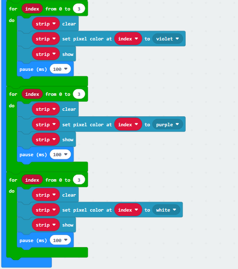
Code 2
|
|---|
“on start”: command block only runs once to start program. |
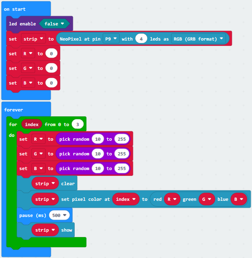
Code 3:
|
|---|
“on start”: command block only runs once to start program. |
Test Results:
Wiring up, dial Voltmeter_Switch to 3V end, plug in external power and dial Power_Switch to ON end.
Download code 1 to micro:bit, WS2812RGB lights display different color.
Download code 2 to micro:bit, WS2812RGB show same color like flow light.
Download code 3 to micro:bit, each WS2812RGB shows random color like flow light.
Project 17: Play Music
Description:
In this project, we will demonstrate how to play music with passive buzzer. Easy Plug shield comes with one. Let’s get started. (Passive buzzer is connected to P0 on Easy Plug shield)
What You Need:
Micro:bit Board*1
EASY Plug Shield for micro bit V1.1*1
Micro USB Cable*1
Slot AA Battery Holder*1
1.5V AA Battery*6
Passive Buzzer Module:
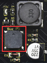
The buzzer includes active buzzer and passive buzzer. The difference between them a built-in vibration source, therefore, it will make a sound when power is plugged in.
We need 2K-5K square wave to drive passive buzzer because the buzzer on EASY Plug Shield doesn’t come with this kind of source.
Different frequencies produce different sounds. You can use the micro:bit to compose a simple, interesting and melodic song.
Specification:
Working voltage: 3.3-5V
Interface type: Digital
Wiring Up:
Note: Dial Voltmeter_Switch to 3V end.
Test Code:
You could navigate https://makecode.micro:bit.org/reference to have access to more details.
Browse link https://makecode.micro:bit.org/ to edit your program. The following test code is as for your reference.
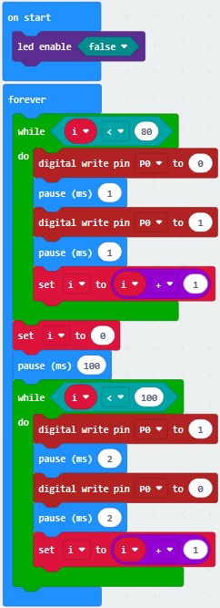
Code 1:
|
“on start”: |
|---|---|
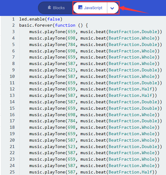
Code 2:
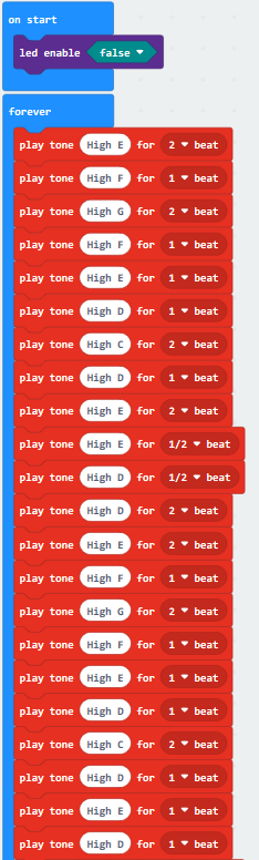
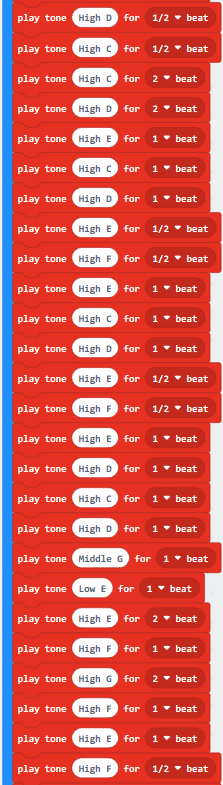
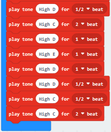
Note: Click to switch into
JavaScript code, each frequency and beat of tone is shown below:
to switch into
JavaScript code, each frequency and beat of tone is shown below:
Test Results:
Wiring up, dial Voltmeter_Switch to 3V end, plug in external power and dial Power_Switch to ON end and upload code 1 to micro:bit, you will hear the buzzer emit two kind of sounds; if download code 2 to micro:bit, the song “Ode to Joy” will be played.
Project 18: Knock Sensor
Description:
Sensor can detect the data, sense the signal and control the devices. We are familiar with light sensor, temperature, humidity and sound sensors. A great deal of experiments could be finished with these sensors and modules.
We will control the LED by knock sensor in the experiment.
What You Need:
Micro:bit Board*1
EASY Plug Shield for micro bit V1.1*1
Micro USB Cable*1
EASY Plug Knock Sensor*1
EASY Plug Red LED Module*1
RJ11 Cable*2
6-Slot AA Battery Holder*1
1.5V AA Battery*6
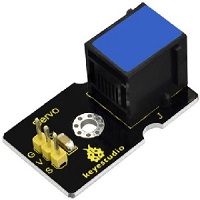
EASY Plug Knock Sensor:
The knock sensor is mainly composed of SW-280 vibration switch, which is an inductive proximity switch.
It is an electronic switch that transmits the sensing result to the circuit device and induces the circuit to start working when the vibration force is induced.
The module comes with a positioning hole for you to fix it to other devices.
You can make full use of it with creative thinking, like electronic drum, and so on.
This module should be used together with EASY plug control board.
Specification:
Interface: Digital
Working voltage: 5V
Sensor type: Easy plug
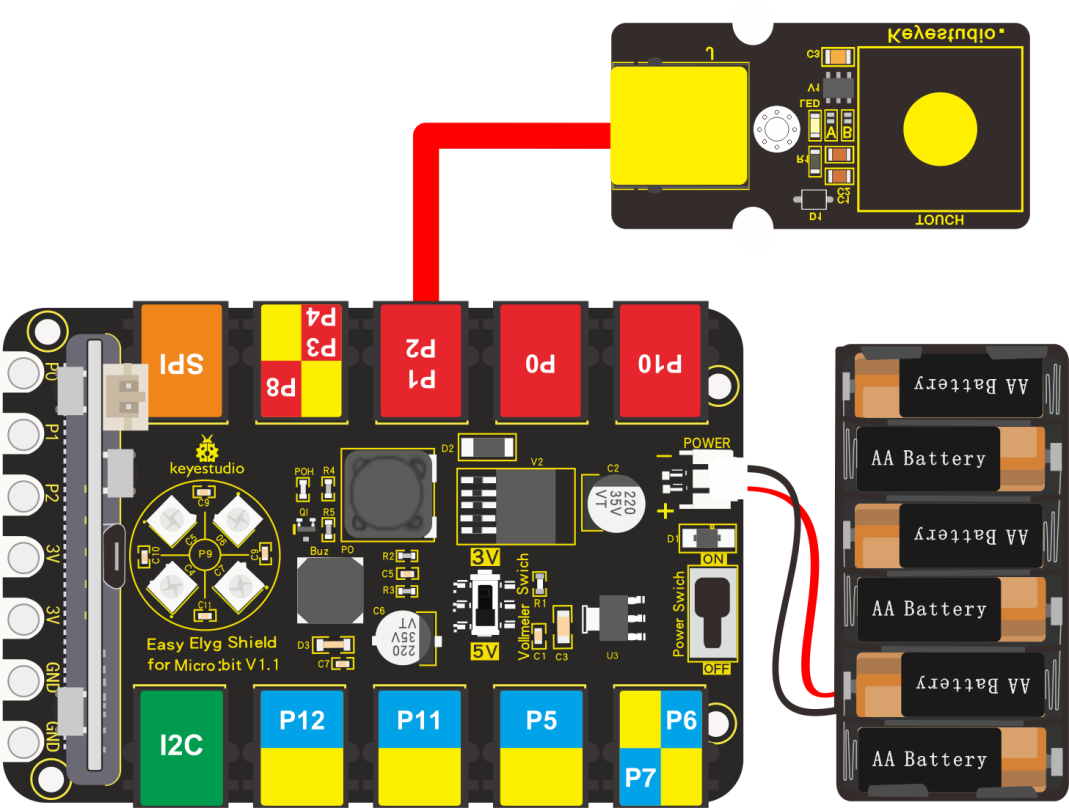
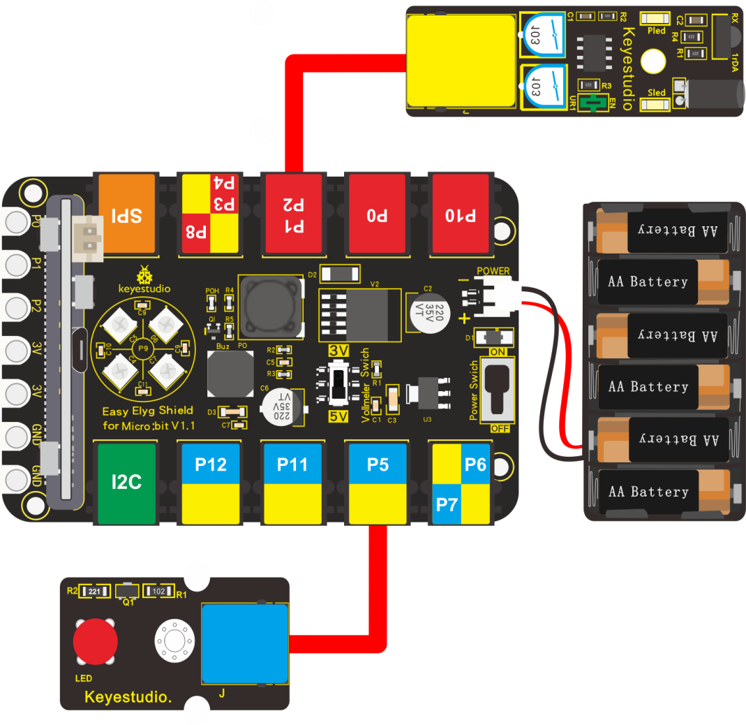
Wiring Up:
Insert micro:bit onto EASY Plug shield, connect knock sensor and red LED module to P1 and P5 port of shield with two RJ11 cables.
Note: Dial Voltmeter_Switch to 3V end.
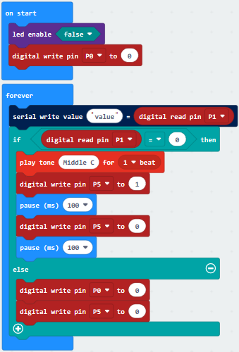
Test Code:
You could navigate https://makecode.micro:bit.org/reference to have access to more details.
Browse link https://makecode.micro:bit.org/ to edit your program. The following test code is as for your reference.
|
“on start”: command block only runs once to start program. |
|---|---|
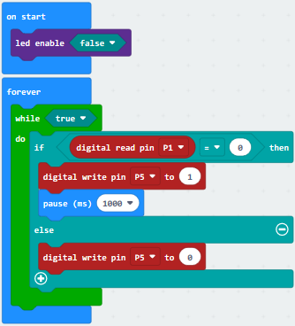
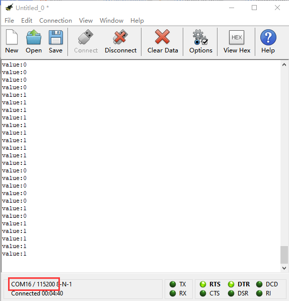
Test Results:
Wiring up, dial Voltmeter_Switch to 3V end, plug in external power and dial Power_Switch to ON end and upload code to micro:bit.
When the module is knocked, LED turns on for 1s; if not, LED is off.
Project 19:Someone Comes
Description:
In this experiment, we connect EASY Plug PIR motion sensor to micro:bit and detect the object moving , the detected digital signals will be displayed on serial monitor.
What You Need:
Micro:bit Board*1
EASY Plug Shield for micro bit V1.1*1
Micro USB Cable*1
EASY Plug PIR Motion Sensor*1
EASY Plug Red LED Module*1
RJ11 Cable*2
6-Slot AA Battery Holder*1
1.5V AA Battery*6
EASY Plug PIR Motion Sensor:
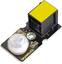
PIR stands for Pyroelectric Infrared (many times, they are also referred as Passive Infrared sensors). This is because their principle of operation is based on the detection of infrared energy emitted by a moving body. The PIR sensor can detect infrared signals from a moving person or moving animal, outputting switching signals.
One important thing to mention is that when motion is detected, the output will stay high for 2.3 to 3 seconds after the motion stops. Regarding the power supply, it can work with voltages of both 3.3V and 5V. The device has a detection range of 7 meters and a detection angle of 100º.
Specification:
Connector: Easy plug
Input Voltage: 3.3 ~ 5V, Maximum 6V
Working Current: 15uA
Working Temperature: -20 ~ 85℃
Output Voltage: High 3V, Low 0V
Output Delay Time (High Level): about 2.3 to 3 Seconds
Detection angle: 100°
Detection distance: 7 meters
Output Indicator LED (When output HIGH, it will be ON)
Pin limit current: 100mA
Wiring Up:
Insert micro:bit onto EASY Plug shield, connect PIR motion sensor and red LED to P1 and P5 port of shield.
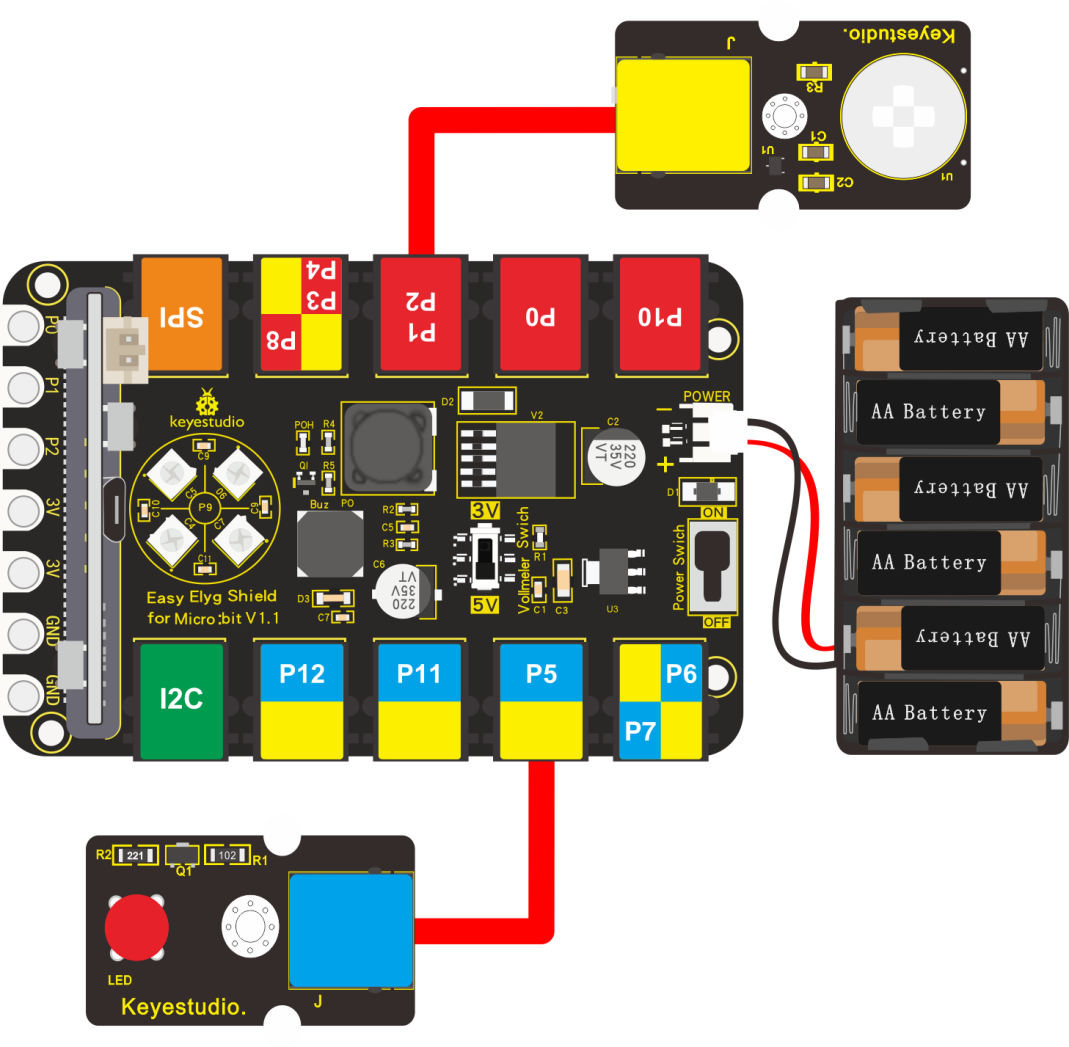
Note: Dial Voltmeter_Switch to 3V end.
Test Code:
You could navigate https://makecode.micro:bit.org/reference to have access to more details.
Browse link https://makecode.micro:bit.org/ to edit your program. The following test code is as for your reference.
|
“on start”: command block only runs once to start program. |
|---|---|
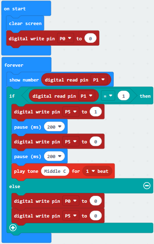
Test Results:
Wiring up, dial Voltmeter_Switch to 3V end, plug in external power and dial Power_Switch to ON end and upload code to micro:bit.
When PIR motion sensor detects the movement of PIR motion sensor. LED flashes, passive buzzer emits sound and micro:bit shows high level(1); by contrast, micro:bit shows low level(0), LED is off and buzzer doesn’t emit sound.
Project 20: Capacitive Touch
Description:
Are you tired of mechanical buttons? Try the capacitive touch module.
In this lesson, we will replace button switch with capacitive touch module and demonstrate how to control passive buzzer with capacitive buzzer.
What You Need:
Micro:bit Board*1
EASY Plug Shield for micro bit V1.1*1
Micro USB Cable*1
EASY Plug Capacitive Touch Module *1
RJ11 Cable*1
6-Slot AA Battery Holder*1
1.5V AA Battery*6
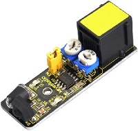
EASY Plug Capacitive Touch Module:
Based on touch detection chip, the touch area of capacitive touch module is applied widely on a plenty of touch sensors. This touch sensor features the one-key button function and adopts the most popular capacitive sensing technology. In addition, it can “feel” people and metal touch and feedback a high/low voltage level. Even isolated by some cloth and paper, it can still feel the touch. The sensitivity will decrease as the isolation getting thick.
This sensor can tackle the traditional button problems, with the characteristics of low consumption and wide working voltage.
Specification:
Jog type: the initial state is low, high touch, do not touch is low (similar touch of a button feature);
Low power consumption;
Power supply for 3.3 ~ 5V DC;
Smooth touch surface
Wiring Up:
Insert micro:bit onto EASY Plug shield, connect capacitive touch module to P1 port of shield.
Note: Dial Voltmeter_Switch to 3V end.
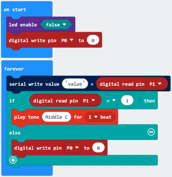
Test Code:
You could navigate https://makecode.micro:bit.org/reference to have access to more details.
Browse link https://makecode.micro:bit.org/ to edit your program. The following test code is as for your reference.
|
“on start”: command block only runs once to start program. |
|---|---|
Test Results:
Wiring up, dial Voltmeter_Switch to 3V end, plug in external power and dial Power_Switch to ON end and upload code to micro:bit.
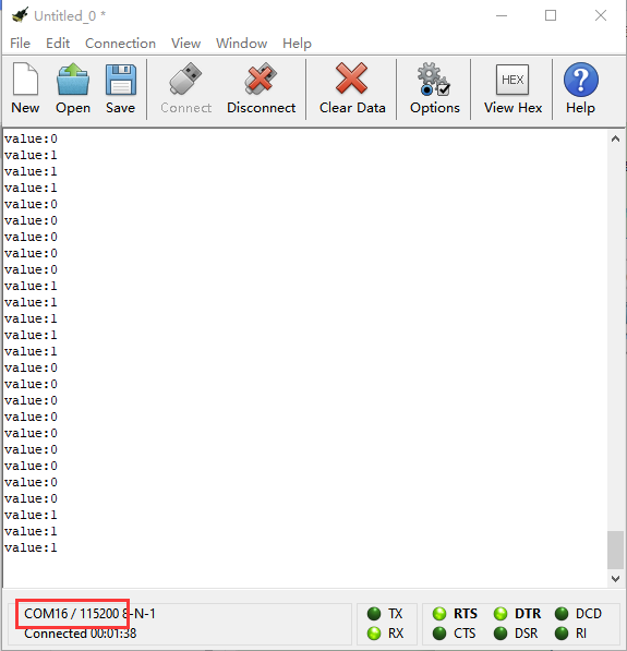
Open CoolTerm, click Options and select SerialPort, set COM port and baud rate, set baud rate to 115200. Tap OK and Connect.
When touch area is touched, CoolTerm monitor shows 1 and passive buzzer emits sound; otherwise, 0 is shown on CoolTerm monitor and passive buzzer doesn’t emit sound, as shown below:
Project 21: Obstacle Avoidance
Description:
Have you ever seen a smart car avoid the obstacle itself?
Do you know why? Let me explain to you in this chapter.
We will use a passive buzzer, red LED module and an obstacle avoidance sensor in the experiment.
What You Need:
Micro:bit Board*1
EASY Plug Shield for micro bit V1.1*1
Micro USB Cable*1
EASY Plug Obstacle Avoidance Sensor*1
EASY Plug Red LED Module*1
RJ11 Cable*2
6-Slot AA Battery Holder*1
1.5V AA Battery*6
Obstacle Avoidance Sensor:
Infrared obstacle avoidance sensor is equipped with distance adjustment function and is especially designed for wheeled robots.
This sensor has strong adaptability to ambient light and is of high precision. It has a pair of infrared transmitting and receiving tube.
When the infrared ray launched by the transmitting tube encounters an obstacle (its reflector), the infrared ray is reflected to the receiving tube, after a comparator circuit processing, the indicator will light up.
You can adjust the detection distance by rotating the potentiometer knob, the effective distance range of 2~40cm.
They can be widely used in robot obstacle avoidance, avoidance car, line count, and black and white line tracking and many other occasions.
Specification:
Working voltage: DC 3.3V-5V
Working current: ≥20mA
Working temperature: -10℃ to+50℃
IO interface: EASY Plug(G(-)/V(+)/out/EN)
Signal output: TTL voltage
Detection distance: 2-40cm
Wiring Up:
Insert micro:bit onto slot of EASY Plug shield, connect obstacle avoidance sensor and red LED module to P1 and P5 of Easy Plug shield.
Note: Dial Voltmeter_Switch to 3V end.
5.Test Code:
You could navigate https://makecode.micro:bit.org/reference to have access to more details.
Browse link https://makecode.micro:bit.org/ to edit your program. The following test code is as for your reference.
|
“on start”: command block only runs once to start program. |
|---|---|
Test Results:
Wiring up, dial Voltmeter_Switch to 3V end, plug in external power and dial Power_Switch to ON end and upload code to micro:bit.
Open CoolTerm, click Options and select SerialPort, set COM port and baud rate, set baud rate to 115200. Tap OK and Connect.
When the obstacle is detected, CoolTerm monitor shows 0 and passive buzzer emits sound and LED flashes ceaselessly; by contrast, CoolTerm monitor displays 1, LED is off, nor the passive buzzer does emit sound.
Project 22: Servo
Description:
In this chapter, we will illustrate the principle and application of servo.
What You Need:
Micro:bit Board*1
EASY Plug Shield for micro bit V1.1*1
Micro USB Cable*1
EASY Plug Servo Module*1
Keyestudio Servo*1
RJ11 Cable*1
6-Slot AA Battery Holder*1
1.5V AA Battery*6
EASY Plug Servo Module:
If you want to use the Micro Servo and EASY PLUG control board to do some experiments, you need to use the EASY Plug Servo extension module.
The EASY Plug Servo module is extended into Registered Jack, so you can connect it to EASY PLUG control board using only a RJ11 cable.
The Servo module also comes with 3pins of 2.54mm pin pitch, fully compatible with servo pins.
Servo:
Servo motor comes with many specifications. But all of them have three connection wires, distinguished by brown, red, orange colors. Brown one is for ground, red one for power positive, orange one for signal line.
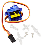
Included with your Micro Servo you will find a variety of white motor mounts that connect to the shaft of your servo.
You may choose to attach any mount you wish for the circuit. It will serve as a visual aid, making it easier to see the servo spin.
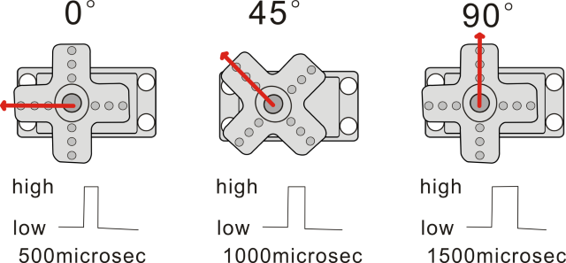
The rotation angle of servo is controlled by regulating the duty cycle of the PWM(Pulse-Width Modulation) signal.
The standard cycle of the PWM signal is fixed at 20ms (50 Hz), and the pulse width is distributed between 1ms-2ms.
The pulse width corresponds to the rotation angle ( 0°~90°) of servo.
Specification:
Operating voltage: DC 4.8V〜6V
Angle range: about 180°(in 500→2500μsec)
Pulsewidth range: 500→2500μsec
No-load speed: 0.12±0.01 sec/60(DC 4.8V); 0.1±0.01 sec/60(DC 6V)
No-load current: 200±20mA(DC 4.8V); 220±20mA(DC 6V)
Stop torque: 1.3±0.01kg/cm(DC 4.8V); 1.5±0.1kg/cm(DC 6V)
Stop current: ≦850mA(DC 4.8V); ≦1000mA(DC 6V)
Standby current: 3±1mA(DC 4.8V); 4±1mA(DC 6V)
Operation temperature: -10℃〜50℃
Save temperature: -20℃〜60℃
Motor wire length: 250 ± 5 mm
Dimensions: 22.9mm*12.2mm*30mm
Weight: 9± 1 g (without servo mounts)
Wiring Up:
Insert micro:bit onto EASY Plug shield, link servo with servo module. Brown line is connected to G, red line is linked with V and orange line is connected to S. Connect servo module to P1 port of shield.
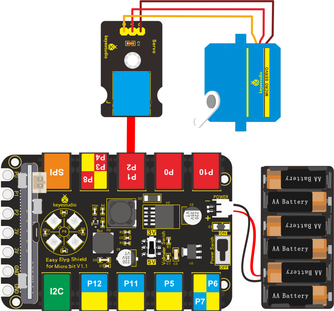
Note:Dial Voltmeter_Switch to 5V end.
Test Code:
You could navigate https://makecode.micro:bit.org/reference to have access to more details.
Browse link https://makecode.micro:bit.org/ to edit your program. The following test code is as for your reference.
|
“on start”: command block only runs once to start program. |
|---|---|
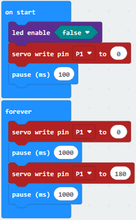
Test Results:
Wiring up, dial Voltmeter_Switch to 5V end, plug in external power and dial Power_Switch to ON end and upload code to micro:bit.
You will view the servo rotate from 0 ° to 180 °
Project 23: Fan Module
Description:
We will make fan module turn clockwise, anticlockwise and stop.
What You Need:
Micro:bit Board*1
EASY Plug Shield for micro bit V1.1*1
Micro USB Cable*1
EASY PlugL9110 Fan Module * 1
RJ11 Cable*1
6-Slot AA Battery Holder*1
1.5V AA Battery*6
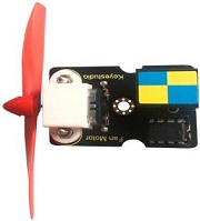
EASY Plug Fan Module:
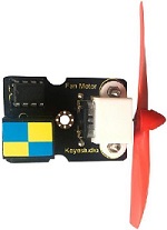
EASY PlugL9110 fan module cooperates GND, VCC, INA and INB pin. Pin INA and INB can control the speed and direction of fan.
This fan control module adopts L9110 motor control chip. It can control the rotation direction of the motor, hence the fan. The module is designed with mounting hole, compatible with servo motor control.
The module is of high efficiency, with the high quality fan, it can easily blow out flame of a light in 20cm distance.
It is widely applied in air propeller, cooling system and spinning frame.
Specification:
Fan blade diameter: 75mm
Interface type: dual analog I/O port interface
Working voltage: 5V
Wiring Up:
Insert micro:bit onto EASY Plug shield, connect fan module to P1-P2 port of shield.
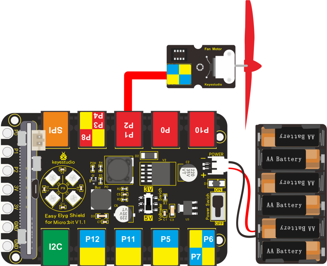
Note: dial Voltmeter_Switch to 5V end.
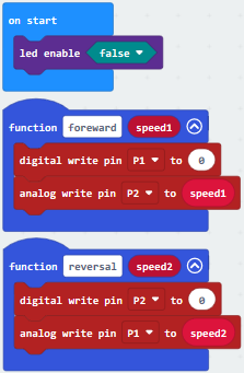
Test Code:
You could navigate https://makecode.micro:bit.org/reference to have access to more details.
Browse link https://makecode.micro:bit.org/ to edit your program. The following test code is as for your reference.
|
“on start”: command block only runs once to start program. |
|---|---|
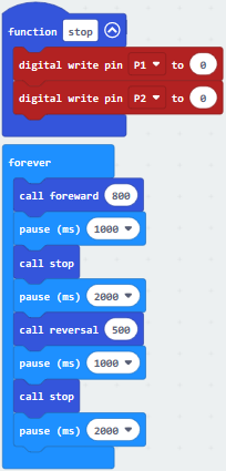
Test Results:
Wiring up, dial Voltmeter_Switch to 5V end, plug in external power and dial Power_Switch to ON end and upload code to micro:bit.
You will view that fan module rotate clockwise for 1s, and stop for 2s, then anticlockwise for 1s, and stop for 2s.
Project 24: Fire Alarm
Description:
The violent fire will cause huge economic and human loss if without any effective measures.
You only need a flame sensor that can alarm if sensing the fire.
In this program, we will imitate the fire alarm system with flame sensor, passive buzzer and red LED module.
What You Need:
Micro:bit Board*1
EASY Plug Shield for micro bit V1.1*1
Micro USB Cable*1
EASY Plug Flame Sensor*1
EASY Plug Red LED Module*1
RJ11 Cable*2
6-Slot AA Battery Holder*1
1.5V AA Battery*6
EASY Plug Flame Sensor:
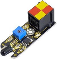
The flame sensor can be used to detect fire or other wavelength at 760nm~1100nm light.
In the fire-fighting robot game, the flame plays an important role in the probe, which can be used as the robot’s eyes to find fire source. The potentiometer on the flame sensor can be used to adjust the sensitivity.
Specification:
Working voltage: 3.3V to 5V
Detection angle: about 60°
Detection range: 20cm (4.8V) ~ 100cm (1V)
Spectral bandwidth: 760nm to 1100nm
Working temperature: -25℃ to 85℃
Sensor type: Easy plug
Interface: digital
Wiring Up:
Insert micro:bit onto Easy Plug shield , connect flame sensor and red LED module to P1 and P5 port of shield with RJ11 cables.
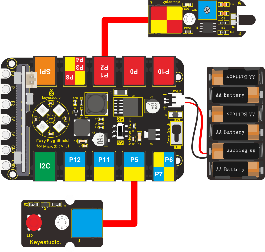 Note: Dial Voltmeter_Switch to 3V end.
Test Code:
You could navigate https://makecode.micro:bit.org/reference to have access to more details.
Browse link https://makecode.micro:bit.org/ to edit your program. The following test code is as for your reference.
|
“on start”: command block only runs once to start program. |
|---|---|
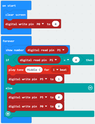
Test Results:
Wiring up, dial Voltmeter_Switch to 3V end, plug in external power and dial Power_Switch to ON end and upload code to micro:bit show 0 (low level), LED is on and passive buzzer emits sound; by contrast.
1 appears on micro:bit, LED is off and buzzer doesn’t emit sound.
Project 25: Flammable Gas in the Air
Description:
This gas sensor is used in gas leakage detecting equipment in consumer electronics and industrial markets.
This sensor is suitable for detecting LPG, I-butane, propane, methane, alcohol, Hydrogen and smoke. It has high sensitivity and quick response. We will show you how to detect the flammable gas in the air with gas sensor.
What You Need:
Micro:bit Board*1
EASY Plug Shield for micro bit V1.1*1
Micro USB Cable*1
EASY Plug Analog Gas Sensor*1
EASY Plug Red LED Module*1
RJ11 Cable*2
6-Slot AA Battery Holder*1
1.5V AA Battery*6
EASY Plug Analog Gas Sensor:
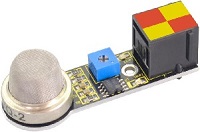
This is a robust Gas sensor suitable for sensing LPG, Smoke, Alcohol, Propane, Hydrogen, Methane and Carbon Monoxide concentrations in the air. If you are planning on creating an indoor air quality monitoring system; breath checker or early fire detection system, Easy Plug gas Sensor Module is a great choice.
It has two signal terminals-pin A0 and D0. The value of A0 will rise up as the concentration of flammable gas.
Specification:
Port: Easy plug
Working Voltage: 5V
Interface Type: Digital and Analog
Wide detecting scope
Simple drive circuit
Stable and long lifespan
Quick response and High sensitivity
Wiring Up:
Insert micro:bit onto EASY Plug shield, connect analog gas sensor and red LED module to P4 and P5 port of shield with RJ11 cables.
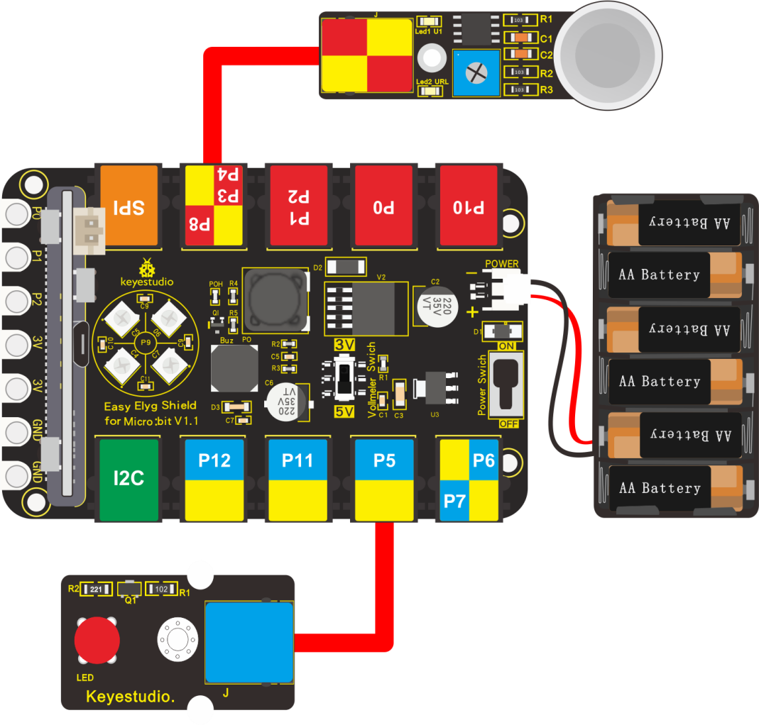
Note: dial Voltmeter_Switch to 5V end.
Test Code:
You could navigate https://makecode.micro:bit.org/reference to have access to more details.
Browse link https://makecode.micro:bit.org/ to edit your program. The following test code is as for your reference.
(Note:the gas analog value could be adjusted)
|
“on start”: |
|---|---|
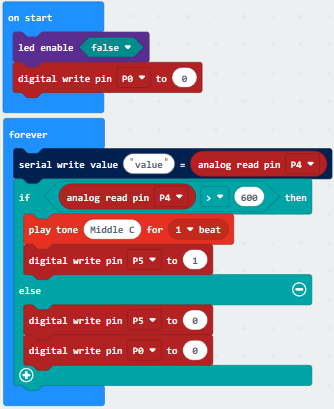
Test Results:
Wiring up, dial Voltmeter_Switch to 5V end, plug in external power and dial Power_Switch to ON end and upload code to micro:bit.
LED2 on gas sensor will be on, you could adjust the sensitivity(make LED at on-and-off state) with blue potentiometer.
Open CoolTerm, click Options and select SerialPort, set COM port and baud rate, set baud rate to 115200. Tap OK and Connect.
Putt the firelighter close to analog gas sensor, the analog value on CoolTerm monitor will get larger and LED1 will be on. When sensor detects the analog value more than 600, buzzer will emit sound; otherwise, buzzer is silent and LED is off.
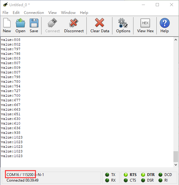
Project 26: Ambient Light
Description:
In this project, we will detect the ambient brightness with EASY PlugTEMT6000 light sensor.
What You Need:
Micro:bit Board*1
EASY PlugShield for micro bit V1.1*1
Micro USB Cable*1
EASY Plug TEMT6000 Ambient Light Sensor*1
RJ11 Cable*1
6-Slot AA Battery Holder*1
1.5V AA Battery*6
EASY Plug TEMT6000:
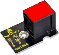
Ambient Light Sensor:
The TEMT6000 was designed as an ambient light detector for automatically controlling the backlight dimming of cell phones, laptops, car dashboards and similar items. It can be used in many applications where it is desirable to measure the relative brightness of the light falling on the sensor.
The sensor is designed to mainly detect the light spectrum visible to the human eye with peak sensitivity at 570nm which is in the green spectrum. The full range spans 440nm to 800nm.
It does react well to very small changes in a wide range of brightness, however, it does not react well to IR or UV light. The sensor can help you to to detect the light density.
Specification:
Working voltage: DC +5v
Communication interface: analog voltage
Only sensitive to visible light, no need for additional filters
Recognizable light intensity range: 1 – 1000 Lux
Good linear output
Wiring Up:
Insert micro:bit onto EASY Plug shield, connect EASY Plug TEMT6000 ambient sensor to P1 port of shield with a RJ11 cable.
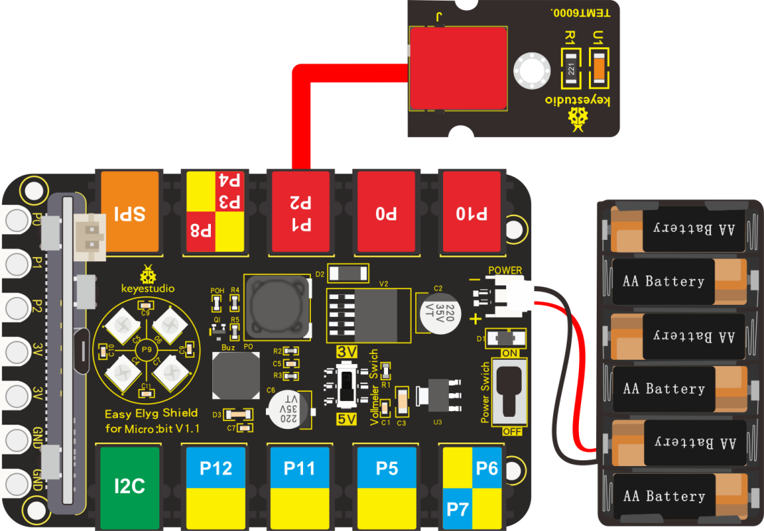
Note: Dial Voltmeter_Switch to 5V end.
Test Code:
You could navigate https://makecode.micro:bit.org/reference to have access to more details.
Browse link https://makecode.micro:bit.org/ to edit your program. The following test code is as for your reference.
|
“on start”: command block only runs once to start program. |
|---|---|
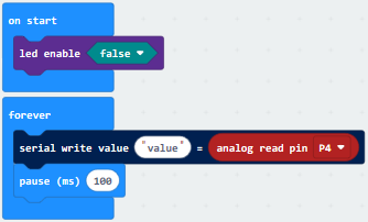
Test Results:
Wiring up, dial Voltmeter_Switch to 5V end, plug in external power and dial Power_Switch to ON end and upload code to micro:bit.(LED2 of sensor shows green color, and you could adjust potentiometer to keep LED on module in off-and-on state(the sensitivity is highest)
Open CoolTerm, click Options and select SerialPort, set COM port and baud rate, set baud rate to 115200. Tap OK and Connect.
The stronger the light is , the larger the analog value is; by contrast, the smaller the analog value is, as shown below:
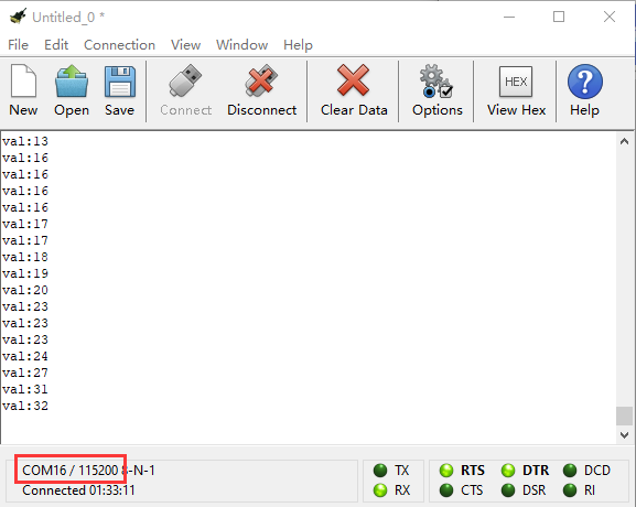
Project 27: Slide Position
Description:
You will learn how to use slide potentiometer to control LED and servo.
What You Need:
Micro:bit Board*1
EASY Plug Shield for micro bit V1.1*1
Micro USB Cable*1
EASY Plug Slide Potentiometer*1
EASY Plug Red LED Module*1
EASY Plug Servo*1
Keyestudio Servo*1
RJ11 Cable*3
6-Slot AA Battery Holder*1
1.5V AA Battery*6
EASY Plug Slide Potentiometer:
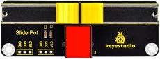
The EASY plug slide potentiometer uses high-quality sliding appliances for stable and reliable performance. It is a dual analog output that outputs a 0-VCC analog voltage signal.
The module pins are extended into Registered jack, so you can easily connect it to EASY Plug control board using a RJ11 cable. There are 6 pad interfaces on the module. So you can solder two 3pin headers with a pitch of 2.54mm on the module.
It can be used to connect with other MCUs. The signal terminal outputs two analog values. The sum of the two analog values is 1023.
Specification:
Working voltage: DC 3.3V-5V
Resistance: 10KΩ
Interface: analog interface
Attribute: ROHS
Wiring Up:
Insert micro:bit onto EASY Plug shield, connect slide potentiometer, red LED module and servo module to P3-P4, P1 and P10 port of shield with RJ11 cables.
The brown line, red line and orange line of servo are respectively connected to G, V and S.
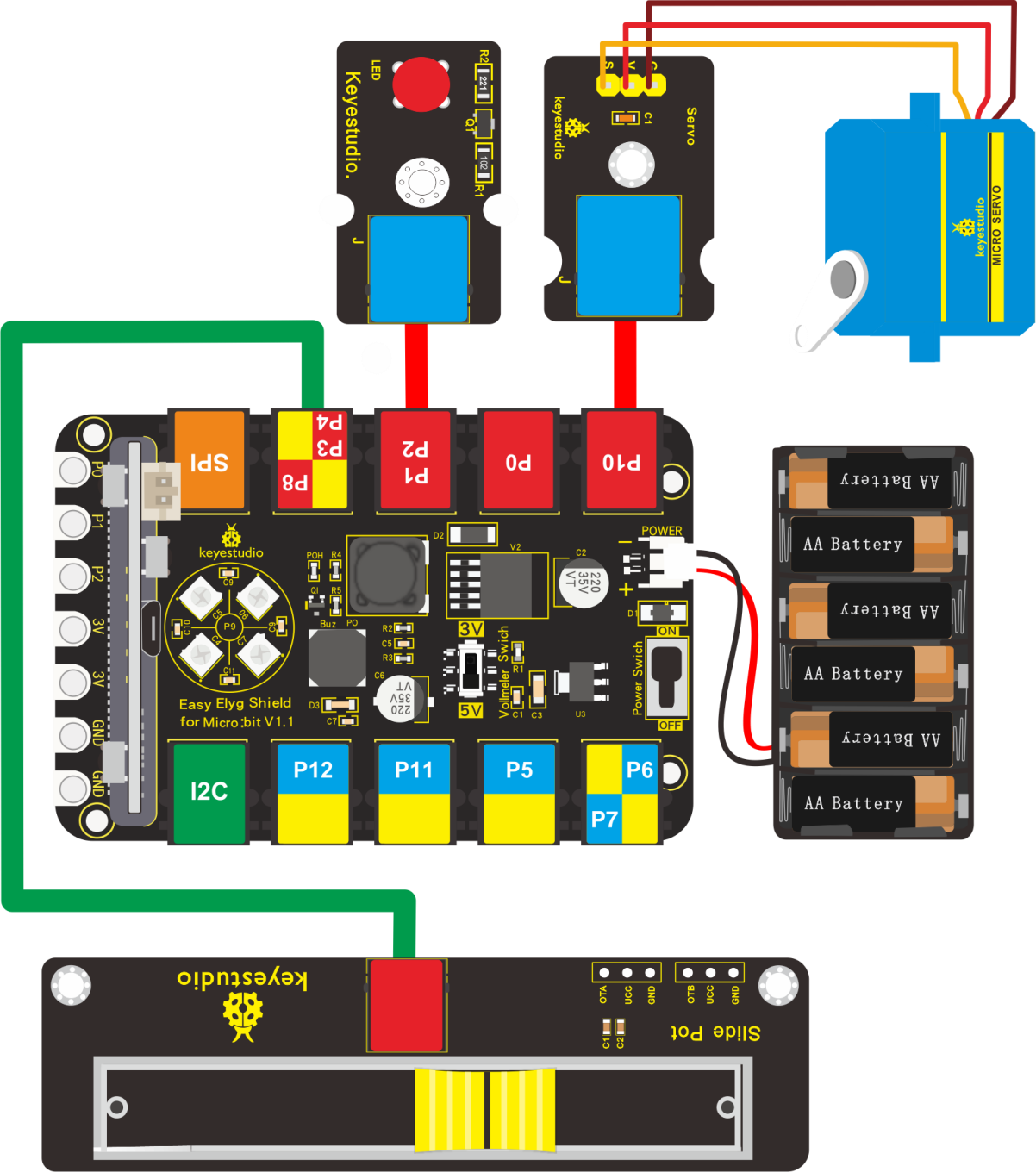
Note: Dial Voltmeter_Switch to 5V end.
Test Code:
You could navigate https://makecode.micro:bit.org/reference to have access to more details.
Browse link https://makecode.micro:bit.org/ to edit your program. The following test code is as for your reference.
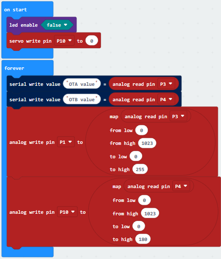
6.Test Results:
Wiring up, dial Voltmeter_Switch to 5V end, plug in external power and dial Power_Switch to ON end and upload code to micro:bit.
Open CoolTerm, click Options and select SerialPort, set COM port and baud rate, set baud rate to 115200. Tap OK and Connect.
CoolTerm monitor displays analog value of pin P3 and P4, if slide the potentiometer, value will alter in 0-1023, and servo will rotate in the range of 0°-180°, as shown below:
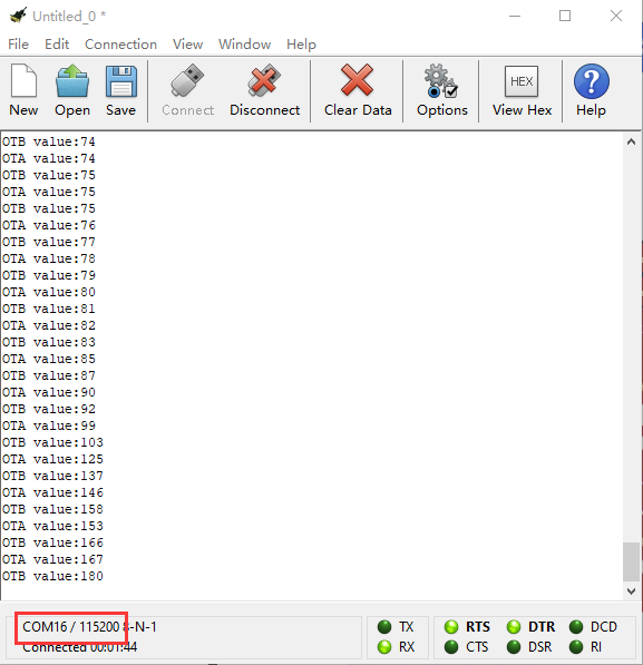
Project 28: Light Brightness
Description:
Sensors are everywhere in our life, street lights will turn on at night but off at day, why? In fact, it is because the photosensitive element that can sense the ambient light brightness. In this program, we will control the light brightness by photoresistor module.
What You Need:
Micro:bit Board*1
EASY Plug Shield for micro bit V1.1*1
Micro USB Cable*1
EASY Plug Photoresistor*1
EASY Plug Red LED Module*1
RJ11 Cable*2
6-Slot AA Battery Holder*1
1.5V AA Battery*6
EASY Plug Photoresistor:
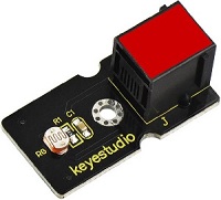
A photoresistor or light-dependent resistor (LDR) or photocell is a light-controlled variable resistor. The principal is very simple. The resistance of photoresistor varies with incident light intensity. If the incident light intensity is high, the resistance decreases; if the light intensity is low, the resistance increases.
keyestudio EASY Plug photocell sensor is a semiconductor, integrated with a photoresistor, easy to use and very convenient for wiring.
It has features of high sensitivity, quick response, spectral characteristic and R-value consistence.
It can be applied in light-sensitive detector circuits, intelligent switch design and light- and dark-activated switching circuits.
Wiring Up:
Insert micro:bit onto EASY Plug shield, connect photoresistor and red LED module to P1 and P10 port of shield with RJ11 cables.
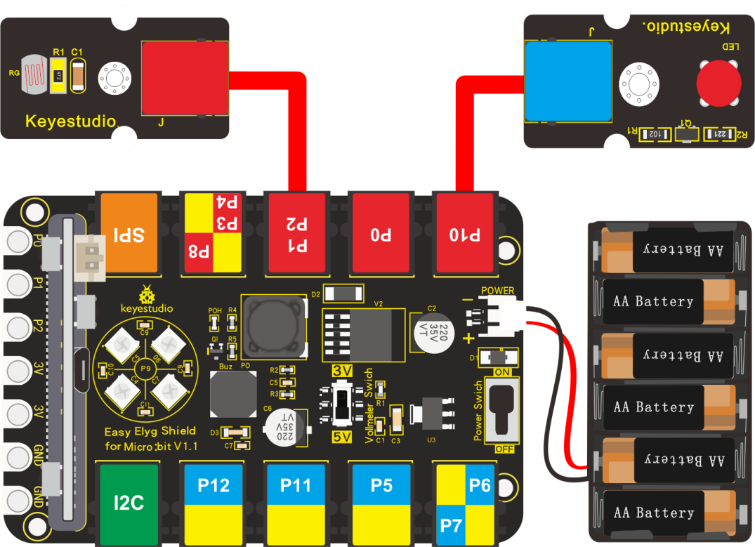
Note: Dial Voltmeter_Switch to 3V end.
Test Code:
You could navigate https://makecode.micro:bit.org/reference to have access to more details.
Browse link https://makecode.micro:bit.org/ to edit your program. The following test code is as for your reference.
|
“on start”: |
|---|---|
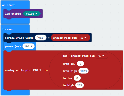
Test Results:
Wiring up, dial Voltmeter_Switch to 3V end, plug in external power and dial Power_Switch to ON end and upload code to micro:bit.
Open CoolTerm, click Options and select SerialPort, set COM port and baud rate, set baud rate to 115200. Tap OK and Connect.
As the ambient light brightness increases, so does the analog value on CoolTerm monitor, red LED gradually gets brighter; by contrast, analog value reduces and LED gets dimmer.
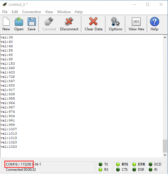
Project 29: OLED Display
Description:
OLED module is applied widely in mobile devices, in this project, we will demonstrate how to display numbers, context and pictures with OLED module.
What You Need:
Micro:bit Board*1
EASY Plug Shield for micro bit V1.1*1
Micro USB Cable*1
EASY Plug OLED Module*1
RJ11 Cable*1
6-Slot AA Battery Holder*1
1.5V AA Battery*6
EASY Plug OLED Module:
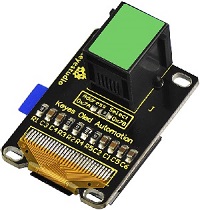
OLED is short for organic light emitting diode. On the microscopic level, an OLED display is a matrix of organic LEDs that light up when they emit energy.
Our EASY Plug OLED displays are perfect when you need a small display with vivid, high-contrast color.
The visible portion of the OLED measures 0.96” diagonal and contains 128 x 64 pixels.
An OLED display works without a backlight. Thus, it can display deep black levels and can be thinner and lighter than a liquid crystal display (LCD).
In low ambient light conditions such as a dark room an OLED screen can achieve a higher contrast ratio than an LCD.
OLED technology is used in commercial applications such as displays for mobile phones and portable digital media players, car radios and digital cameras among others.
Specification:
0.96” diagonal OLED
Pixels: 128 × 64
Color Depth: Monochrome (White)
5V power
Brightness (cd/m2): 100 (Typ)
Wiring Up:
Insert micro:bit onto EASY Plug shield, connect OLED module to I2C port of shield with a RJ11cable.
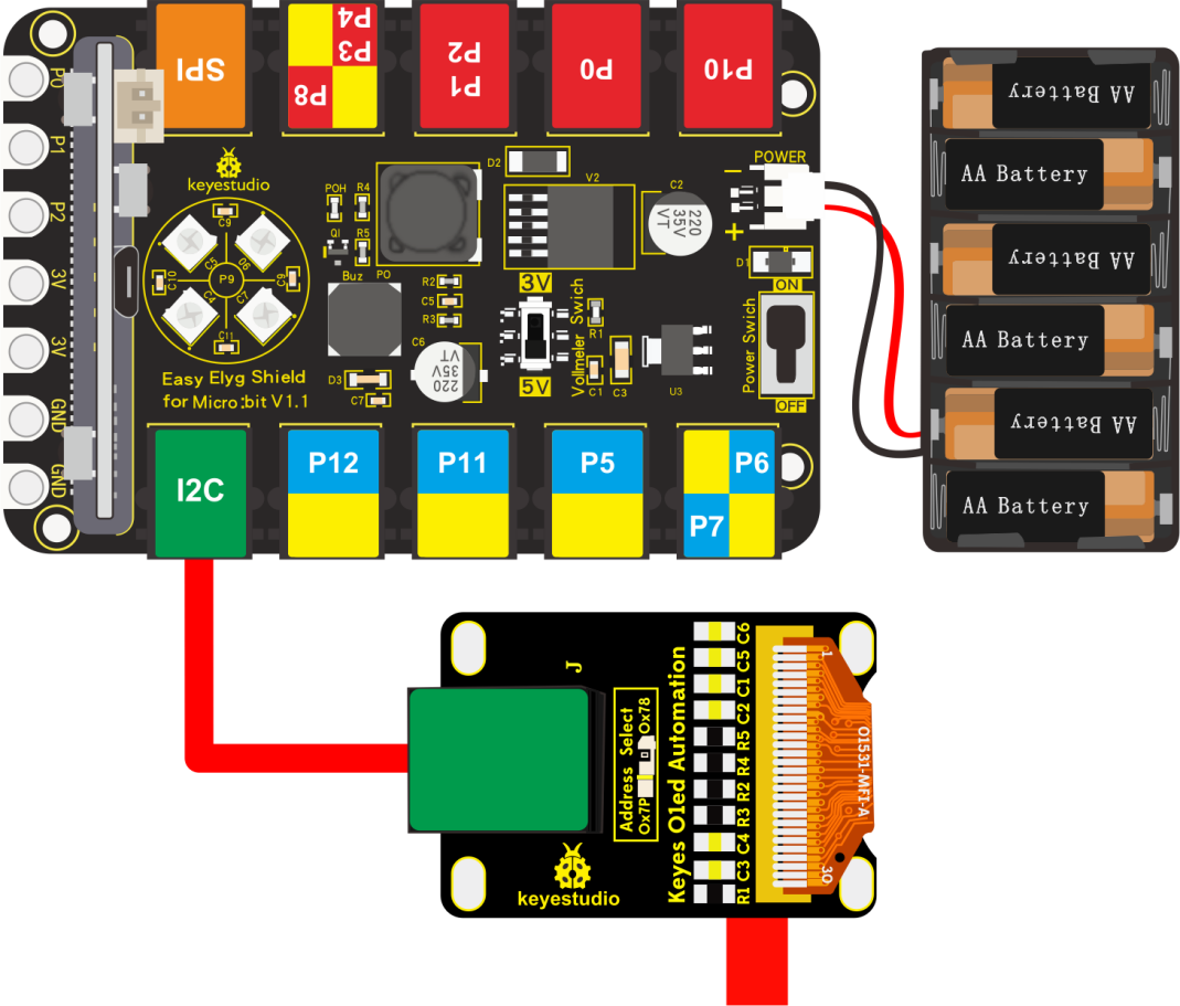
Note: Dial Voltmeter_Switch to 5V end.
Test Code:
You could navigate https://makecode.micro:bit.org/reference to have access to more details.
Browse link https://makecode.micro:bit.org/ to edit your program. The following test code is as for your reference.
Next, we need to add the library file of OLED module:
Search “OLED”, as shown below, select the first “oled -ssd1306” library file, and install library.
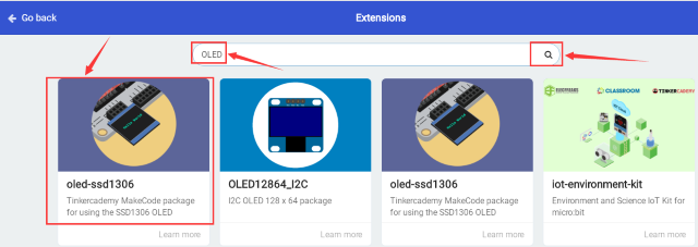
After the installation, the library of OLED module will be displayed in the listed blocks on Makecode editor.
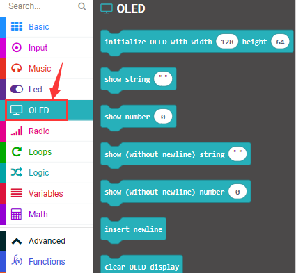
Complete Code:
|
“on start”: command block only runs once to start program. |
|---|---|
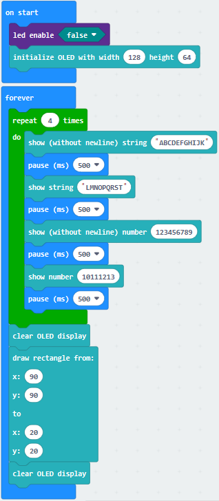
Test Results:
Wiring up, dial Voltmeter_Switch to 5V end, plug in external power and dial Power_Switch to ON end and upload code to micro:bit.
OLED display will show the corresponding characters and pictures.
Project 30: Water Your Plant
Description:
This is a simple soil humidity sensor aims to detect the soil humidity.
If the soil is in lack of water, the analog value output by the sensor will decrease; otherwise, it will increase. If you use this sensor to make an automatic watering device, it can detect whether your botany is thirsty to prevent it from withering when you go out.
What You Need:
Micro:bit Board*1
EASY Plug Shield for micro bit V1.1*1
Micro USB Cable*1
EASY Plug Soil Humidity Sensor*1
EASY Plug OLED Module*1
RJ11 Cable*2
Slot AA Battery Holder*11.5V AA Battery*6
EASY Plug Soil Humidity Sensor:
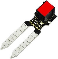
The EASY Plug soil moisture sensor can read the amount of moisture present in the soil surrounding it. It’s an ideal for monitoring an urban garden, or your pet plant’s water level.
This soil moisture sensor uses the two probes to pass current through the soil, and then it reads that resistance to get the moisture level.
More water makes the soil conduct electricity more easily (less resistance), while dry soil conducts electricity poorly (more resistance).
If you use this sensor to make an automatic watering device, it will be helpful to remind you to water your indoor plants or to monitor the soil moisture in your garden.
Specification:
Working voltage: 3.3V-5V
Working current: ≤ 20mA
Output voltage: 0-2.3V (The greater the humidity, the higher the output voltage.)
Sensor type: Analog output
Automotive Watering System:
We connect a soil humidity sensor and a relay module to MCU.
Separately link water pump and power on NO end of relay module. When the soil lacks the water, MCU controls relay module(NO is connected) to drive water pump to water plant; if the soil is wet enough, NO is cut off, water pump stops watering plant.
Wiring Up:
Insert micro:bit onto EASY Plug shield, connect soil humidity sensor and OLED module to P1 and I2C port of shield.
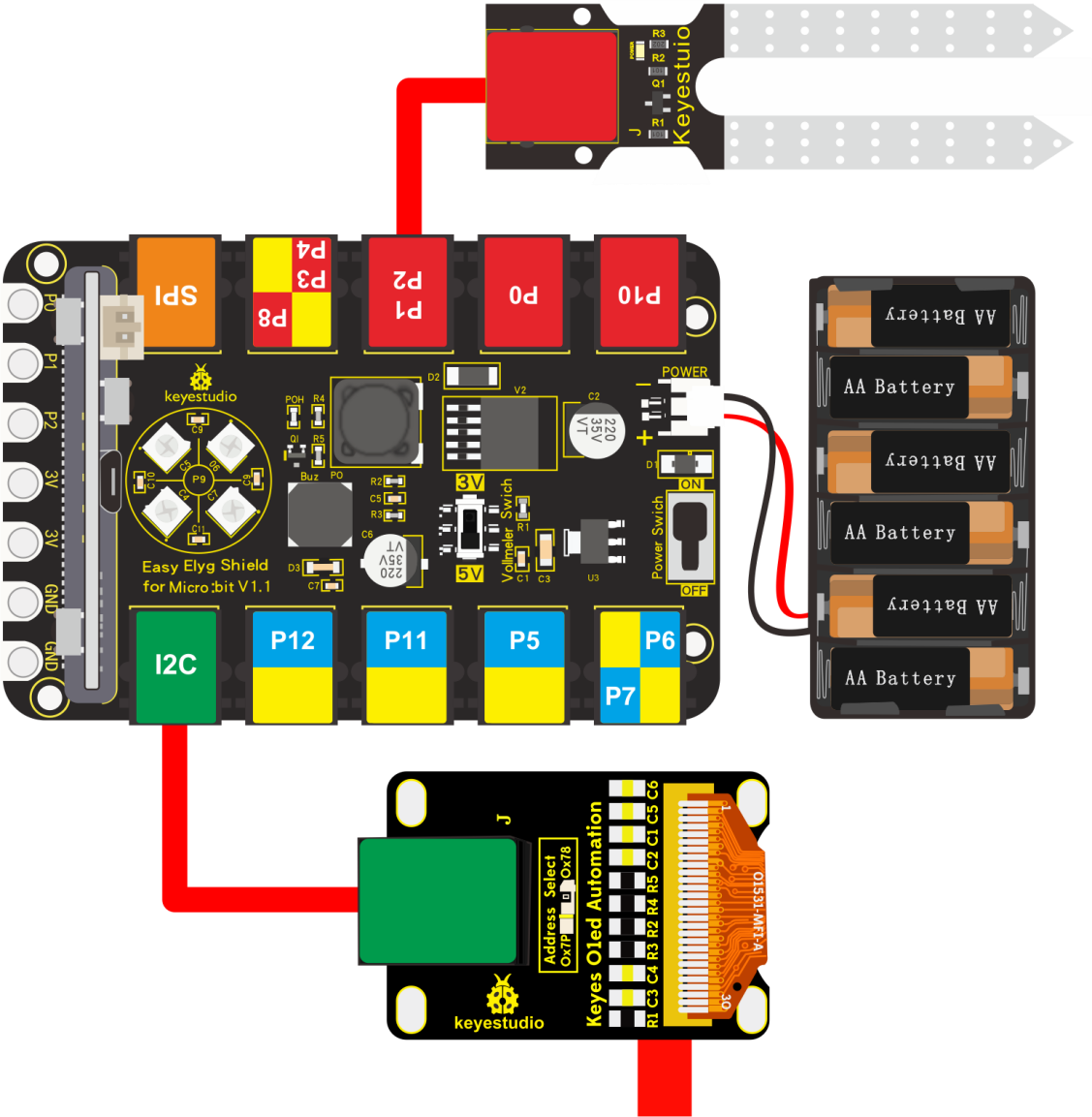
Note: Dial Voltmeter_Switch to 5V end.
Test Code:
You could navigate https://makecode.micro:bit.org/reference to have access to more details.
Browse link https://makecode.micro:bit.org/ to edit your program. The following test code is as for your reference.
Search “OLED”, as shown below, select “oled -ssd1306” library and install it.
After the installation, you will view the OLED in the listed blocks.
Complete Code:
|
“on start”: command block only runs once to start program. |
|---|---|
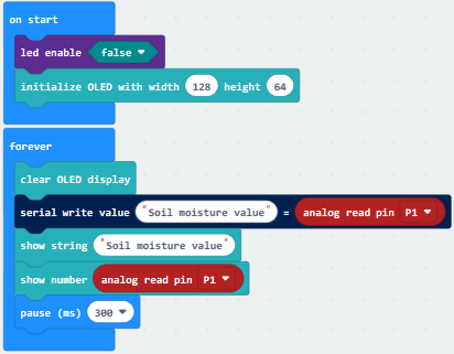
Test Results:
Wiring up, dial Voltmeter_Switch to 5V end, plug in external power and dial Power_Switch to ON end and upload code to micro:bit.
Open CoolTerm, click Options and select SerialPort, set COM port and baud rate, set baud rate to 115200. Tap OK and Connect.
Insert the soil humidity sensor into soil, CoolTerm monitor and OLED module will display the analog value of soil humidity. As the humidity rises up, so does the analog value; otherwise, the analog sol humidity value will gradually decreases.
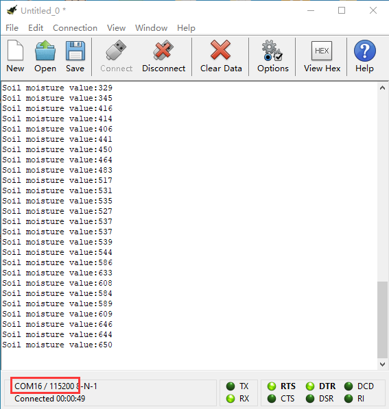
Project 31: Ultrasonic Ranging
Description:
Ultrasonic sensor can detect the distance. In this program, we will conduct you how to detect the distance with it.
What You Need:
Micro:bit Board*1
EASY Plug Shield for micro bit V1.1*1
MicroUSB Cable*1
EASY Plug Ultrasonic Sensor*1
RJ11 Cable*1
6-Slot AA Battery Holder*1
1.5V AA Battery*6
EASY Plug Ultrasonic Sensor:
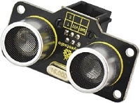
The ultrasonic module will emit the ultrasonic waves after trigger signal. When the ultrasonic waves encounter the object and are reflected back, the module outputs an echo signal, so it can determine the distance of object from the time difference between trigger signal and echo signal.
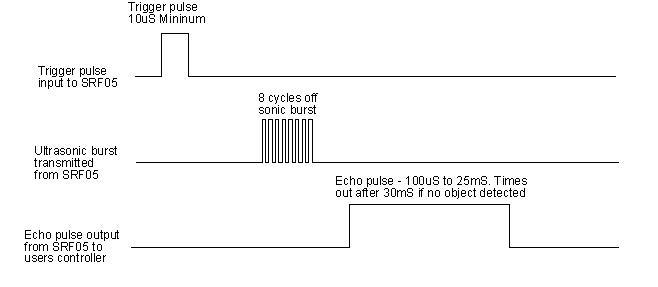
Use method and timing chart of ultrasonic module:
Setting the delay time of Trig pin of SR04 to 10μs at least, which can trigger it to detect distance.
After triggering, the module will automatically send eight 40KHz ultrasonic pulses and detect whether there is a signal return. This step will be completed automatically by the module.
If the signal returns, the Echo pin will output a high level, and the duration of the high level is the time from the transmission of the ultrasonic wave to the return.
the distance measured by ultrasonic wave = (speed * time) / 2 .
Specification:
Power Supply :+5V DC
Quiescent Current : <2mA
Working Current: 15mA
Effectual Angle: <15°
Ranging Distance : 2cm – 400 cm
Resolution : 0.3 cm
Measuring Angle: 30 degree
Trigger Input Pulse width: 10uS
Output echo signal: output TTL level(high), proportional to distance
Interface:dual digital I/O port
Wiring Up:
Insert micro:bit onto EASY Plug shield, connect an ultrasonic sensor to P1-P2 of shield.
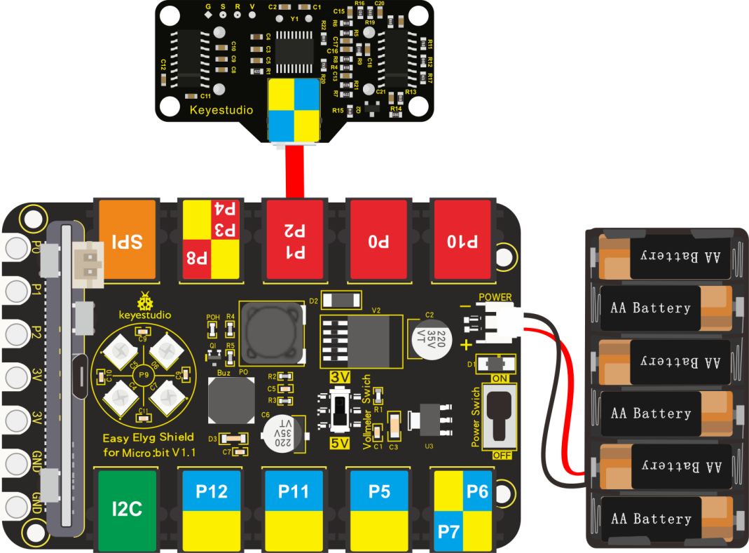
Note: Dial Voltmeter_Switch to 5V end.
Test Code:
You could navigate https://makecode.micro:bit.org/reference to have access to more details.
Browse link https://makecode.micro:bit.org/ to edit your program. The following test code is as for your reference.
Code 1:
|
“on start”: |
|---|---|
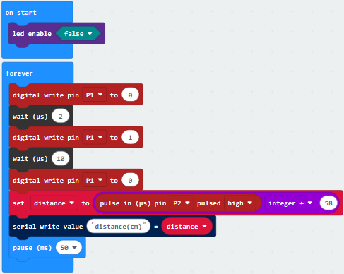
Code 2:
Next to add the library of ultrasonic sensor, click “Extensions”
Search “sonar”,and click sonar library to download it.
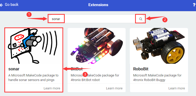
After the installation, you will view it appear in the listed blocks on Makecode editor.
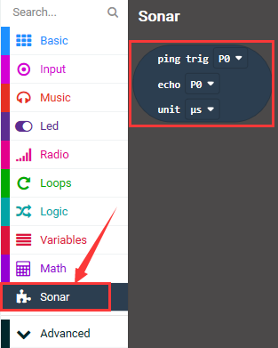
Complete Code:
|
|
|---|---|
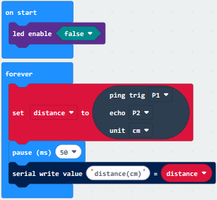
Test Results:
Wiring up, dial Voltmeter_Switch to 3V end, plug in external power and dial Power_Switch to ON end and upload code 1 and 2 to micro:bit.
Open CoolTerm, click Options and select SerialPort, set COM port and baud rate, set baud rate to 115200. Tap OK and Connect.
Micro:bit and CoolTerm monitor will display the current temperature, as shown below:
CoolTerm monitor will display the distance value.
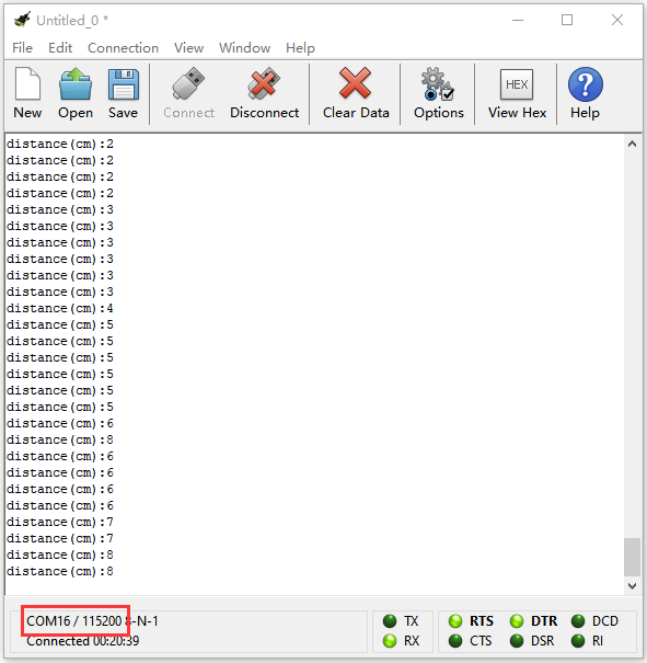
Project 32: IR Remote Control Decoding
Description:
Every mad scientist’s lab, or teenager’s secret room, needs advanced protection against intrusion by rogue agents or siblings. If you are one of them, you should probably consider getting a Passive infrared (PIR) sensor for you. PIR sensors allow you to detect when someone is in your room when they shouldn’t be.
What You Need:
Micro:bit Board*1
EASY Plug Shield for micro bit V1.1*1
Micro USB Cable*1
EASY Plug IR Receiver Module*1
EASY Plug IR Remote Control*1
RJ11 Cable*1
6-Slot AA Battery Holder*1
1.5V AA Battery*6
EASY Plug IR Receiver Module:
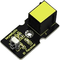
There is no doubt that infrared remote control is ubiquitous in daily life. It is used to control various household appliances, such as TVs, stereos, video recorders and satellite signal receivers. Infrared remote control is composed of infrared transmitting and infrared receiving systems, that is, an infrared remote control and infrared receiving module and a single-chip microcomputer capable of decoding.
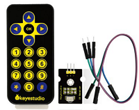
The 38K infrared carrier signal emitted by remote controller is encoded by the encoding chip in the remote controller. It is composed of a section of pilot code, user code, user inverse code, data code, and data inverse code. The time interval of the pulse is used to distinguish whether it is a 0 or 1 signal and the encoding is made up of these 0, 1 signals.
The user code of the same remote control is unchanged. The data code can distinguish the key.
When the remote control button is pressed, the remote control sends out an infrared carrier signal. When the IR receiver receives the signal, the program will decode the carrier signal and determines which key is pressed. The MCU decodes the received 01 signal, thereby judging what key is pressed by the remote control.
Infrared receiver we use is an infrared receiver module. Mainly composed of an infrared receiver head, it is a device that integrates reception, amplification, and demodulation. Its internal IC has completed demodulation, and can achieve from infrared reception to output and be compatible with TTL signals. Additionally, it is suitable for infrared remote control and infrared data transmission. The infrared receiving module made by the receiver has only three pins, signal line, VCC and GND. It is very convenient to communicate with arduino and other microcontrollers.
Specification:
Interface: Easy plug
Working voltage: 5V Interface
Type: DigitaL
Modulation frequency: 38Khz
Wiring Up:
Insert micro:bit onto EASY Plug shield, connect an IR receiver module toP12 port of shield.
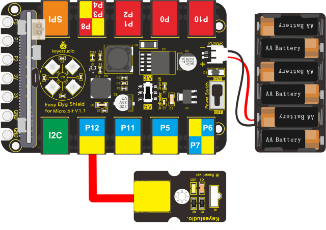
Note: Dial Voltmeter_Switch to 5V.
Test Code:
You could navigate https://makecode.micro:bit.org/reference to have access to more details.
Browse link https://makecode.micro:bit.org/ to edit your program. The following test code is as for your reference.
Next, we need to add the library of IR receiver module.
Click “Extensions” on Makecode editor.
Enter the library link: Copy https://github.com/keyestudio-team/pxt-RI-receiver.git and search, and download “keyestudio-IR-remote” file.
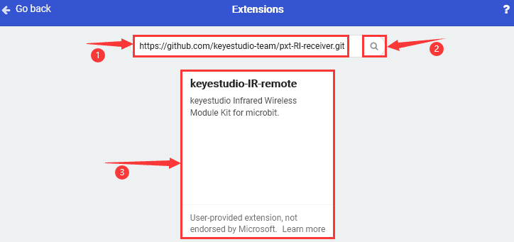
After the installation, you will see the “IR remote” in the listed blocks.
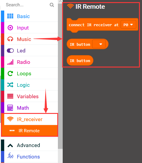
Complete Code:
|
“on start”: command block only runs once to start program. |
|---|---|
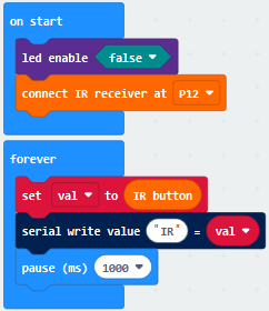
Code explanation: serial monitor will refresh and show 0, when the key is not pressed; when it is pressed, CoolTerm will show the corresponding value.
Note:
Battery is not included, you need to make a purchase it (model: CR2025).
Make sure IR remote control is good, open camera on your cellphone, point IR remote control to camera and press button. It is good if you see purple light flashing.
Test Results:
Wiring up, dial Voltmeter_Switch to 5V end, plug in external power and dial Power_Switch to ON end and upload code to micro:bit.
Open CoolTerm, click Options and select SerialPort, set COM port and baud rate, set baud rate to 115200. Tap OK and Connect.
CoolTerm monitor will display the corresponding key values, as shown below:
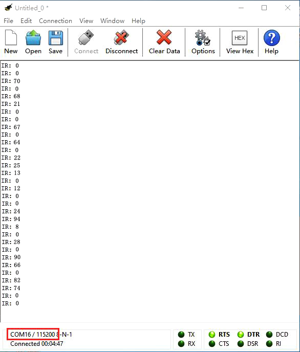
Below we have listed out each button value of keyestudio remote control. So you can keep it for reference.
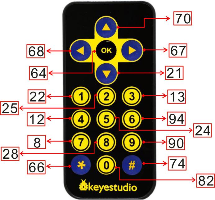
Project 33: IR Remote Control RGB
Description:
We decode the IR remote control with an IR receiver module and a micro:bit board before doing experiment. We could get key values which can control the external sensors/ modules after decoding IR remote control. In this experiment, we control 2812 2x2 full color RGB of shield with these key values.
What You Need:
Micro:bit Board*1
EASY Plug Shield for micro bit V1.1*1
Micro USB Cable*1
EASY Plug IR Receiver*1
EASY Plug IR Remote Control*1
RJ11 Cable*1
6-Slot AA Battery Holder*1
1.5V AA Battery*6
Wiring Up:
Insert micro:bit onto EASY Plug shield, connect IR receiver to P12 port to shield with a RJ11 cable.
Note: Dial Voltmeter_Switch to 5V end.
Test Code:
You could navigate https://makecode.micro:bit.org/reference to have access to more details.
Browse link https://makecode.micro:bit.org/ to edit your program. The following test code is as for your reference.
Next, we need to add the library file of IR receiver module.
Click “Extensions” on Makecode.
Enter the library link https://github.com/keyestudio-team/pxt-RI-receiver.git and search, as shown below,download the file.
Then you could view the library of IR receiver module in the listed blocks.
Repeat the above steps to add the library of “neopixel”:
Click “Extensions” → “neopixel”, after second, install the library of “neopixel”.
Complete Code:
|
“on start”: |
|---|---|
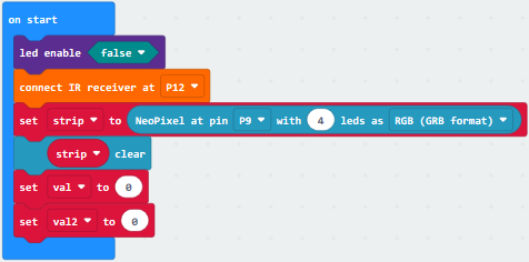
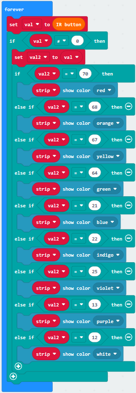
Test Results:
Wire up, plug in power, dial Voltmeter_Switch to 5V end and upload code to micro:bit.
Point IR remote control to IR receiver and press keys.
Key |
Status |
2812 2x2 full-color RGB |
|---|---|---|
|
Press |
Red Color |
|
Press |
Orange Color |
|
Press |
Yellow Color |
|
Press |
Green Color |
|
Press |
Blue Color |
|
Press |
Indigo Color |
|
Press |
Violet Color |
|
Press |
Purple Color |
|
Press |
White Color |


Project 34: Joystick
Description:
Lots of robot projects need joystick. This module provides an affordable solution.
By simply connecting to two analog inputs, the robot is at your commands with X, Y control. It also has a switch that is connected to a digital pin.
What You Need:
Micro:bit Board*1
EASY Plug Shield for micro bit V1.1*1
Micro USB Cable*1
EASY Plug Joystick Module*1
RJ11 Cable*1
6-Slot AA Battery Holder*1
1.5V AA Battery*6
EASY Plug Joystick Module:
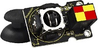
This is a joystick very similar to the‘analog’ joysticks on PS2 (PlayStation 2) controllers. It is a self-centering spring loaded joystick, meaning when you release the joystick it will center itself. It also contains a comfortable cup-type knob/cap which gives the feel of a thumb-stick.
The goal of the joystick is to communicate motion in 3D (3-axis) to an Arduino. This is achieved by housing two independent 10K potentiometers (one per axis). These potentiometers are used as dual adjustable voltage dividers, providing x and y axis analog input in a control stick form.
This joystick also contains a switch which activates when you push down on the cap. The switch is the small black box on the rear of the joystick.
The basic idea of a joystick is to translate the stick’s position on three axes — the X-axis (left to right), the Y-axis(front and back) into electronic information an Arduino can process and the Z-axis(up and down).
Specification:
Interface: Easy plug
Working voltage: 3.3V to 5V
Interface type: analog port and digital port
Wiring Up:
Insert micro:bit onto EASY Plug shield and connect joystick module to P3-P4-P8 port of shield with a RJ11 cable.
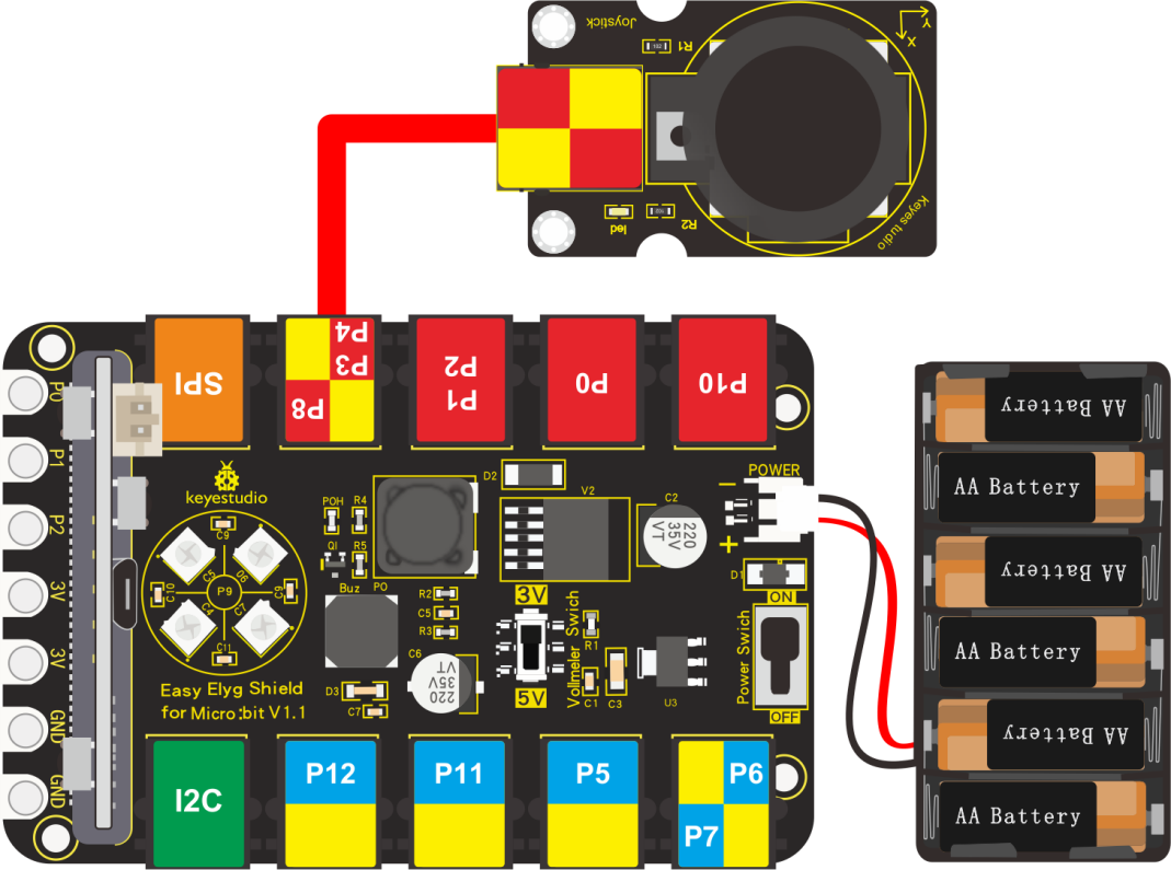
Note: Dial Voltmeter_Switch to 3V end.
Test Code:
You could navigate https://makecode.micro:bit.org/reference to have access to more details.
Browse link https://makecode.micro:bit.org/ to edit your program. The following test code is as for your reference.
|
“on start”: |
|---|---|
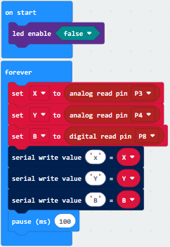
Test Results:
Wiring up, dial Voltmeter_Switch to 3V end, plug in external power and dial Power_Switch to ON end and upload code to micro:bit.
Open CoolTerm, click Options and select SerialPort, set COM port and baud rate, set baud rate to 115200. Tap OK and Connect.
CoolTerm monitor shows the analog value on x, y axis and pin B.
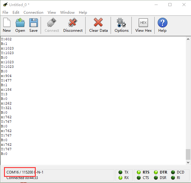
Project 35: What Time Is It?
Description:
In this program, we will demonstrate how to read time by combing DS3231 clock module with micro:bit. You will view the time on CoolTerm monitor.
What You Need:
Micro:bit Board*1
EASY Plug Shield for micro bit V1.1*1
Micro USB Cable*1
EASY Plug DS3231 Clock Module*1
RJ11 Cable*1
6-Slot AA Battery Holder*1
1.5V AA Battery*6
EASY Plug DS3231 Clock Module:
The DS3231 is a low-cost, extremely accurate I2C real-time clock (RTC) with an integrated temperature-compensated crystal oscillator (TCXO) and crystal. A real-time clock (RTC) is a computer clock (most often in the form of an integrated circuit) that keeps track of the current time.
At the heart of the module is a low-cost, extremely accurate RTC chip from Maxim – DS3231. It manages all timekeeping functions and features a simple two-wire I2C interface which can be easily interfaced with any microcontroller of your choice.
The chip maintains seconds, minutes, hours, day, date, month, and year information. The date at the end of the month is automatically adjusted for months with fewer than 31 days, including corrections for leap year (valid up to 2100).
The clock operates in either the 24-hour or 12-hour format with an AM/PM indicator. It also provides two programmable time-of-day alarms and one programmable square wave output.
The DS3231 incorporates a battery input, and maintains accurate timekeeping when main power to the device is interrupted.
The built-in power-sense circuit continuously monitors the status of VCC to detect power failures and automatically switches to the backup supply. So, you need not worry about power outages, your MCU can still keep track of time.
EASY Plug DS3231 module integrates pin GND, VCC, SDA and SCL for easily wiring up and can communicate with MCUs in synchronic and serial way.
SCL is a serial clock pin for I2C interface.
SDA is a serial data pin for I2C interface.
VCC pin supplies power for the module.
GND is a ground pin.
Specification:
Temperature range: -40℃ to +85℃
Timing accuracy: about ± 5ppm
Output: 1Hz and 32.768kHz
High speed (400kHz), I2C serial bus
Supply voltage: 3.3V to 5.5V
Output Level: TTL level
Wiring Up:
Insert micro:bit onto EASY Plug shield, connect DS3231 clock module to I2C port of shield with a RJ11 cable.
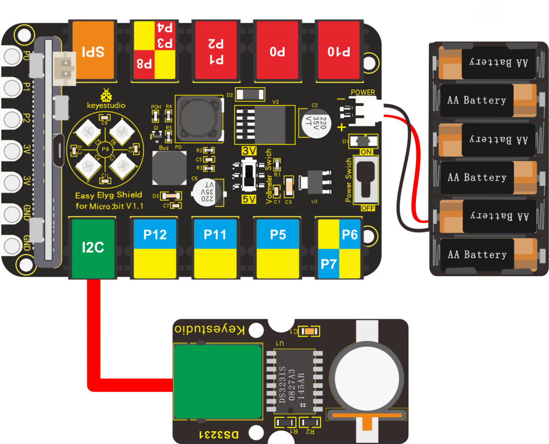
Note: Dial Voltmeter_Switch to 5V end.
Test Code:
You could navigate https://makecode.micro:bit.org/reference to have access to more details.
Browse link: https://makecode.micro:bit.org/ to edit your program. The following test code is as for your reference.
Need to set test code, therefore, let’s add the library of DS3231 clock module.
Set code with library file, click “Extensions”.
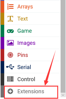
Enter library link: https://github.com/keyestudio-team/pxt-DS3231 and search it, download it as follows:
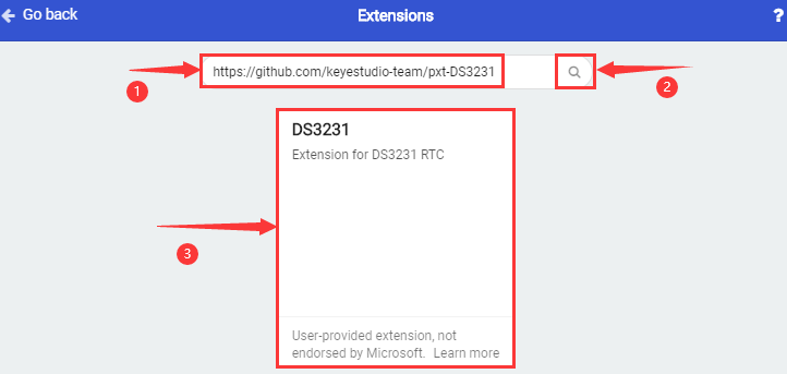
After the installation, you could see it in the listed blocks on Makecode editor.
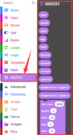
Complete Code:
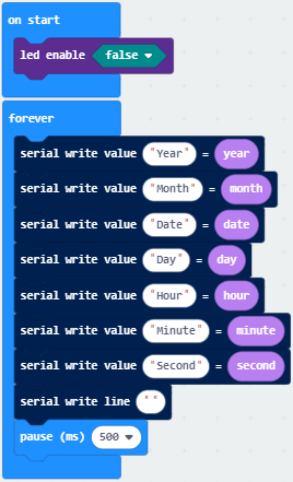
Test Results:
Wiring up, dial Voltmeter_Switch to 5V end, plug in external power and dial Power_Switch to ON end and upload code to micro:bit.
Open CoolTerm, click Options and select SerialPort, set COM port and baud rate, set baud rate to 115200. Tap OK and Connect.
CoolTerm monitor will display time(year/month/day/week/hour/minute/second), as shown below: